Small Word Clock Kitをプログラミング ー PICマイコン入門 ー
本記事にはアフィリエイト広告が含まれます。
先日 Makerfabs 様よりいただいたSmall Word Clock Kitを自分でプログラミングできるように下ごしらえ致しました。
目次
Small Word Clock Kit
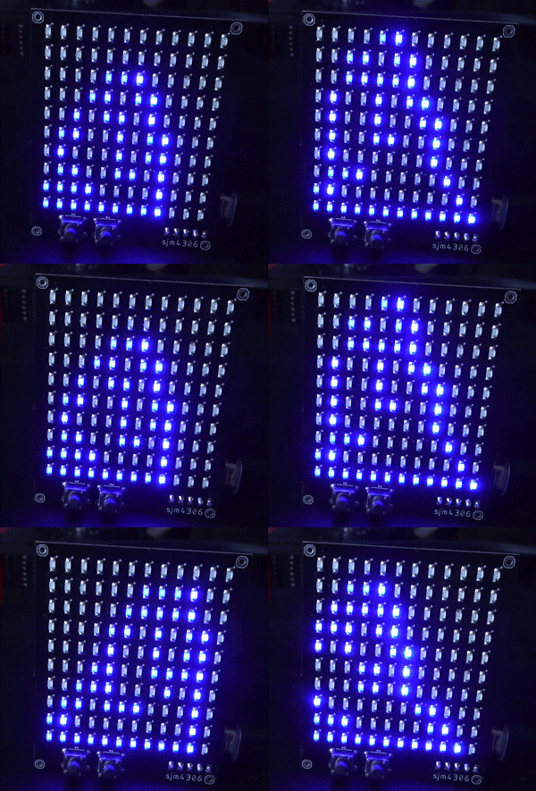
Small Word Clock Kitには12×10のLEDマトリクスが仕込まれており
文字で時刻などを表示します。
制御にはPIC16F887が用いられており、
RTCの時刻記憶用の電池にはCR1220が使用されています。
外観図面や回路図、ファームは以下に上がっています。
回路図
PICマイコン
Small Word Clock KitにはPIC16F887が使用されています。
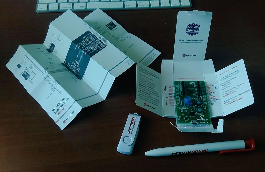
PICマイコンを取り扱うのは初めてでしたので諸々準備いたしました。
PICライタ
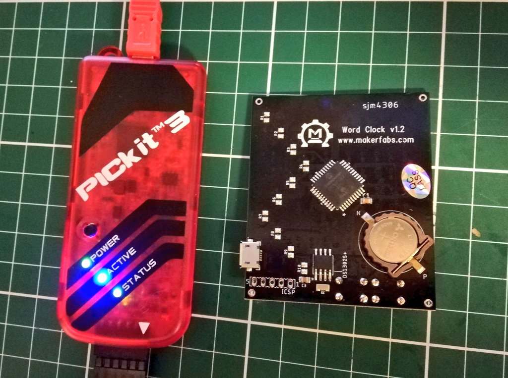
PICマイコンにコードを書き込むためにライタが必要になります。
以下を購入いたしました。
純正品ではないですが、問題なく使用できました。
PCへUSBケーブルで接続し、Small Word Clock KitへはICSP端子に接続します。
初めてのPICマイコン
鬼門はいつだって環境構築#Makerfabs pic.twitter.com/NG0sZoY7KR— HomeMadeGarbage (@H0meMadeGarbage) May 22, 2020
MPLAB
PICマイコン用統合開発環境ソフトウェアMPLAB X IDEをインストールいたします。
以下を参考にインストールいたしました。バージョンはv5.40。
書き込み時にPICライタから電源供給するようにしました(4.75V)。
http://www.maibun.org/~nt/technicalnote/debian7/pickit3.html
PICマイコン用のCコンパイラーのMPLAB XC8もインストールします。
バージョンはv1.45。v2.20ではコンパイル時にエラーが出ました。
参考
Lチカ
簡単にコードを描いてみてLED一個を点灯させてみました。
Lチカ やっと出来た pic.twitter.com/03eWQzZnrD
— HomeMadeGarbage (@H0meMadeGarbage) May 24, 2020
参考
動作
4つのLEDで”HOME”と点灯させています。
コード
前述のhackaday.ioにアップされているコード (word clock v1.1.zip)
を参考にいたしました。
|
1 2 3 4 5 6 7 8 9 10 11 12 13 14 15 16 17 18 19 20 21 22 23 24 25 26 27 28 29 30 31 32 33 34 35 36 37 38 39 40 41 42 43 44 45 46 47 48 49 50 51 52 53 54 55 56 57 58 59 60 61 62 63 64 65 66 67 68 69 70 71 72 73 74 75 76 77 78 79 80 81 82 83 84 85 86 87 88 89 90 91 92 93 94 95 96 97 98 99 100 101 102 103 104 105 106 107 108 109 110 111 112 113 114 115 116 117 |
#include <xc.h> #pragma config WDTE=OFF,PWRTE=OFF,CP=OFF,BOREN=OFF,DEBUG=OFF,FCMEN=OFF #pragma config LVP=OFF,MCLRE=ON,CPD=OFF,IESO=OFF,FOSC=INTRC_NOCLKOUT #pragma config BOR4V=BOR21V,WRT=OFF //関数__delay用周波数指定 #define _XTAL_FREQ 8000000 #define P0 RA4 //LED Matrix Anodes (row) #define P1 RA5 #define P2 RE0 #define P3 RE1 #define P4 RE2 #define P5 RA6 #define P6 RA7 #define P7 RD2 #define P8 RD3 #define P9 RC4 #define N0 RB0 //LED Matrix Cathodes (column) #define N1 RB1 #define N2 RB2 #define N3 RB3 #define N4 RB4 #define N5 RB5 #define N6 RC5 #define N7 RA3 #define N8 RA2 #define N9 RA1 #define N10 RA0 #define N11 RD0 void delay(long x){ //quick delay function (blocking) while(x>0){ x--; } } void set_column_IO(unsigned int column){ TRISA=0b00001111;TRISB=0b11111111;TRISC=0b00100000;TRISD=0b00000001; //set all columns to Hi-Z switch(column){ case 0: //set N0 as output, rest Hi-Z TRISB0=RB0=0;break; case 1: //set N1 as output, rest Hi-Z TRISB1=RB1=0;break; case 2: //set N2 as output, rest Hi-Z TRISB2=RB2=0;break; case 3: //set N3 as output, rest Hi-Z TRISB3=RB3=0;break; case 4: //set N4 as output, rest Hi-Z TRISB4=RB4=0;break; case 5: //set N5 as output, rest Hi-Z TRISB5=RB5=0;break; case 6: //set N6 as output, rest Hi-Z TRISC5=RC5=0;break; /////////Super important gotcha, columns 6-11 had weird itermittant issue fixed here by rewriting cathodes to 0 case 7: //set N7 as output, rest Hi-Z TRISA3=RA3=0;break; case 8: //set N8 as output, rest Hi-Z TRISA2=RA2=0;break; case 9: //set N9 as output, rest Hi-Z TRISA1=RA1=0;break; case 10: //set N10 as output, rest Hi-Z TRISA0=RA0=0;break; case 11: //set N11 as output, rest Hi-Z TRISD0=RD0=0;break; } } void set_rows(unsigned int row){ //row is 16 bits but only lower 10 bits are used if(row&0x001){P0=1;}else{P0=0;} //read buffered display array to correctly set anodes if(row&0x002){P1=1;}else{P1=0;} if(row&0x004){P2=1;}else{P2=0;} if(row&0x008){P3=1;}else{P3=0;} if(row&0x010){P4=1;}else{P4=0;} if(row&0x020){P5=1;}else{P5=0;} if(row&0x040){P6=1;}else{P6=0;} if(row&0x080){P7=1;}else{P7=0;} if(row&0x100){P8=1;}else{P8=0;} if(row&0x200){P9=1;}else{P9=0;} } void main(void) { OSCCON=0x71; // 8MHz TRISA=0x00; TRISB=0xC0; TRISC=0x00; TRISD=0x00; TRISE=0x00; PORTA=0x00; PORTB=0x00; PORTC=0x00; PORTD=0x00; PORTE=0x00; while(1){ for(int i = 0; i < 5000; i++){ set_column_IO(1); set_rows(0x002); set_column_IO(6); set_rows(0x002); set_column_IO(11); set_rows(0x002); set_column_IO(3); set_rows(0x004); } set_rows(0); __delay_ms(500); } } |
出荷時の動作に戻す
コンパイル済みのファームフェアがhackaday.ioに上がっています。
word clock.hex
コンパイル済みのファームはMPLAB X IDEと同時にインストールされるMPLAB X IPEで書き込みます。


