Small Word Clock Kitをプログラミング ー Party Parrot ー
本記事にはアフィリエイト広告が含まれます。
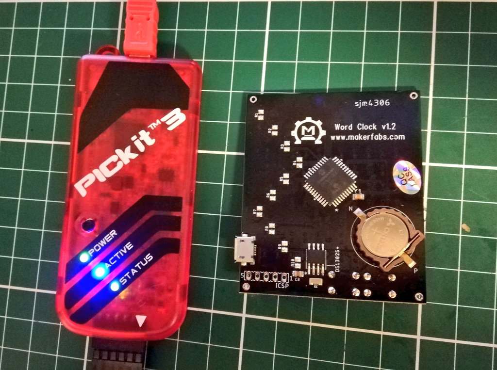
前回は Makerfabs 様よりいただいたSmall Word Clock Kitを自分でプログラミングできるように開発環境を整えました。
今回は好きな画像を表示できるようにいたしました。
Party Parrot
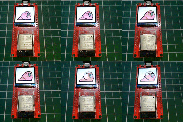
ここでは Party Parrot を表示できるようにいたしました。
素材(chillparrot.gif)は以下で入手いたしました。
https://cultofthepartyparrot.com/
Small Word Clock Kitの12×10のLEDマトリクスに表示するために、gifをBMPに分解して12×10に縮小しました。
gitの画像の4枚分を加工してバイナリにして、Small Word Clock Kitに書き込みました。
Small Word Clock Kitのメモリ的に4枚が限界でした。
マイコンはPIC16F887が搭載されており、メモリは14KBです。
Arduino UNO (32KB )より少ないんですよね。
コード
前回と同様に、PICマイコン用統合開発環境ソフトウェアMPLABでコーディングしました。
myBitmapがParty Parrotの4枚のバイナリデータです。
|
1 2 3 4 5 6 7 8 9 10 11 12 13 14 15 16 17 18 19 20 21 22 23 24 25 26 27 28 29 30 31 32 33 34 35 36 37 38 39 40 41 42 43 44 45 46 47 48 49 50 51 52 53 54 55 56 57 58 59 60 61 62 63 64 65 66 67 68 69 70 71 72 73 74 75 76 77 78 79 80 81 82 83 84 85 86 87 88 89 90 91 92 93 94 95 96 97 98 99 100 101 102 103 104 105 106 107 108 109 110 111 112 113 114 115 116 117 118 119 120 121 122 123 124 125 126 127 128 129 130 131 132 133 134 135 136 137 138 139 140 141 142 143 144 145 146 147 148 149 150 151 |
#include <xc.h> #pragma config WDTE=OFF,PWRTE=OFF,CP=OFF,BOREN=OFF,DEBUG=OFF,FCMEN=OFF #pragma config LVP=OFF,MCLRE=ON,CPD=OFF,IESO=OFF,FOSC=INTRC_NOCLKOUT #pragma config BOR4V=BOR21V,WRT=OFF //関数__delay用周波数指定 #define _XTAL_FREQ 8000000 #define P0 RA4 //LED Matrix Anodes (row) #define P1 RA5 #define P2 RE0 #define P3 RE1 #define P4 RE2 #define P5 RA6 #define P6 RA7 #define P7 RD2 #define P8 RD3 #define P9 RC4 #define N0 RB0 //LED Matrix Cathodes (column) #define N1 RB1 #define N2 RB2 #define N3 RB3 #define N4 RB4 #define N5 RB5 #define N6 RC5 #define N7 RA3 #define N8 RA2 #define N9 RA1 #define N10 RA0 #define N11 RD0 void delay(long x){ //quick delay function (blocking) while(x>0){ x--; } } void set_column_IO(unsigned int column){ TRISA=0b00001111;TRISB=0b11111111;TRISC=0b00100000;TRISD=0b00000001; //set all columns to Hi-Z switch(column){ case 0: //set N0 as output, rest Hi-Z TRISB0=RB0=0;break; case 1: //set N1 as output, rest Hi-Z TRISB1=RB1=0;break; case 2: //set N2 as output, rest Hi-Z TRISB2=RB2=0;break; case 3: //set N3 as output, rest Hi-Z TRISB3=RB3=0;break; case 4: //set N4 as output, rest Hi-Z TRISB4=RB4=0;break; case 5: //set N5 as output, rest Hi-Z TRISB5=RB5=0;break; case 6: //set N6 as output, rest Hi-Z TRISC5=RC5=0;break; /////////Super important gotcha, columns 6-11 had weird itermittant issue fixed here by rewriting cathodes to 0 case 7: //set N7 as output, rest Hi-Z TRISA3=RA3=0;break; case 8: //set N8 as output, rest Hi-Z TRISA2=RA2=0;break; case 9: //set N9 as output, rest Hi-Z TRISA1=RA1=0;break; case 10: //set N10 as output, rest Hi-Z TRISA0=RA0=0;break; case 11: //set N11 as output, rest Hi-Z TRISD0=RD0=0;break; } } void set_rows(unsigned int row){ //row is 16 bits but only lower 10 bits are used if(row == 0){ P0=1; }else if(row == 1){ P1=1; }else if(row == 2){ P2=1; }else if(row == 3){ P3=1; }else if(row == 4){ P4=1; }else if(row == 5){ P5=1; }else if(row == 6){ P6=1; }else if(row == 7){ P7=1; }else if(row == 8){ P8=1; }else if(row == 9){ P9=1; }else{ P0=0; P1=0; P2=0; P3=0; P4=0; P5=0; P6=0; P7=0; P8=0; P9=0; } } int wait = 10; int brightness = 6; unsigned int myBitmap [4][10] = { {0xfff, 0xc3f, 0xc1f, 0x94f, 0x96f, 0x867, 0xae3, 0xb89, 0xbfc, 0x800}, {0xfcf, 0xf93, 0xf83, 0xf2d, 0xe6d, 0xecd, 0xefd, 0xdf1, 0xbfc, 0x000}, {0xfff, 0xfe3, 0xfc1, 0xfc8, 0xf9a, 0xfa7, 0xfa7, 0xe7e, 0xcf8, 0x800}, {0xfff, 0xfff, 0xf8f, 0xf27, 0xf4b, 0xe59, 0xe5d, 0xe99, 0xef0, 0xe00} }; void main(void) { OSCCON=0x71; // 8MHz TRISA=0x00; TRISB=0xC0; TRISC=0x00; TRISD=0x00; TRISE=0x00; PORTA=0x00; PORTB=0x00; PORTC=0x00; PORTD=0x00; PORTE=0x00; while(1){ for(int frame = 0; frame < 4; frame++){ for(int i = 0; i < wait; i++){ for(int y = 0; y < 10; y++){ int a = 0; for(int x = 0b1; x <= 0b100000000000; x *=2){ if(!(myBitmap[frame][y] & x)){ set_column_IO(a); set_rows(y); } a++; } for(int b = 0; b < brightness; b++){} set_rows(10); } } } } } |
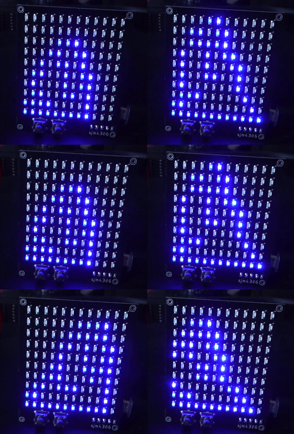
動作
解像度12×10でちょっと粗すぎますが、雰囲気はでていますww
ついにPICマイコン搭載のSmall Word Clock KitのLEDマトリクスに自由自在なる表示ができるようになりました(恐らく)!!
お父ちゃん![]() にとって初のPICマイコン製品でしたので大変うれしいです。
にとって初のPICマイコン製品でしたので大変うれしいです。
隣にあるのは、以前おいじりしたMakePython ESP32 Color LCDです。

