姿勢制御検討 ードローンへの道2ー
本記事にはアフィリエイト広告が含まれます。
前回は Makerfabs 様よりいただいた基板 ESP32 6- Axis IMU を用いてドローン製作を決意いたしました。
ここではプロペラを制御してドローンの姿勢を制御するべく検討いたしましたので報告します。
目次
モータ回転
ESP32 6- Axis IMU にモータとプロペラを接続し、回転動作を確認します。
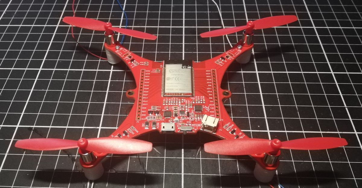
モータ番号の配置と回転方向そしてIOピンの割り振りは以下の通りです。
使用したモータとプロペラは以下です。
動作
ESP32のモータ駆動ピンにPWM信号を入力して回転させてみました。
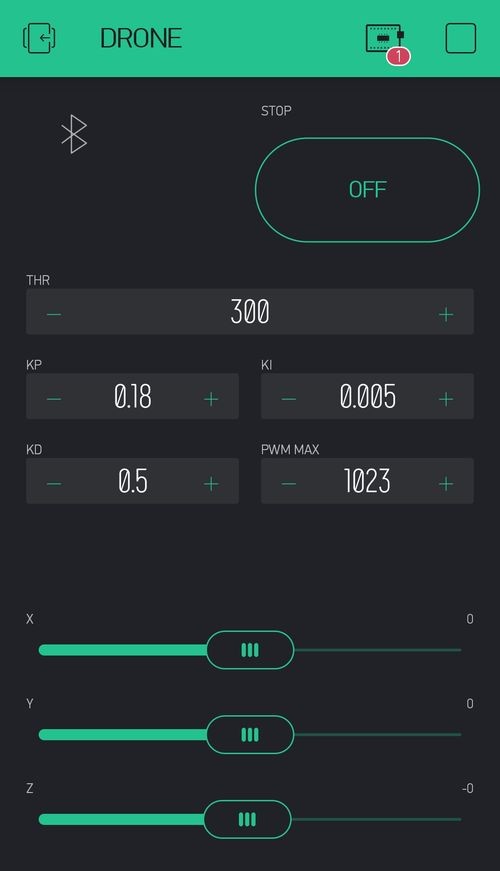
スマホアプリ Blynk を用いてBLE通信でPWM信号のデューティを指定しています。
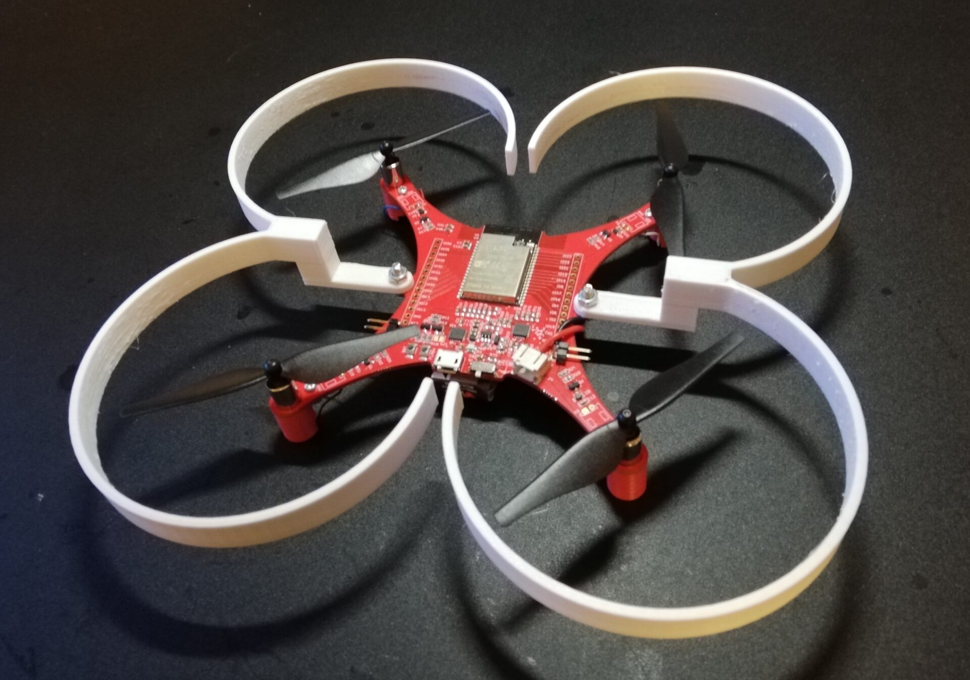
このまま飛ばしてみました。
なんか嫌な道に入っちまったな おい#ドローンへの道 pic.twitter.com/uEPEWvMzRg
— HomeMadeGarbage (@H0meMadeGarbage) January 4, 2021
当然ただモータぶん回すだけじゃこうなりますよね。。。
ちなみにダイソーのワイヤーネットで飛行実験場をこしらえました。
ドローン実験場
制作費 770円#ダイソー pic.twitter.com/ydfSOF2PhW
— HomeMadeGarbage (@H0meMadeGarbage) January 4, 2021
姿勢制御
何となく飛びそうなことがわかりましたので、姿勢制御で安定飛行を目指します。
MPU6050
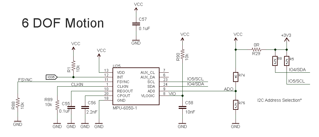
ESP32 6- Axis IMU には6軸IMUセンサ MPU6050が搭載されています。
軸は以下の通りです。
MPU6050のArduinoライブラリは以下を使用しました。
https://github.com/jrowberg/i2cdevlib/tree/master/Arduino/MPU6050
https://github.com/jrowberg/i2cdevlib/tree/master/Arduino/I2Cdev
ここではMPU6050のDMP (Digital Motion Processor) 機能を使用して姿勢角を検出することにします。
DMPは内部で何をしているかはよくわかりませんが品質の高い姿勢情報を容易に得ることができます、
モータ制御
XYZ軸の傾きに応じてモータを制御してドローンの姿勢を制御します。
各軸のフィードバック値はそれぞれの姿勢角と角速度を用いては以下のようにPID制御で求めることにしました。
$$軸のフィードバック値 = Kp × (θ – θ_{target}) + Ki × \sum{ (θ – θ_{target})} + Kd × ω$$
$θ$は各軸の角度、$θ_{target}$は目標とする姿勢角、$ω$は各軸の角速度、Kは各パラメータの係数です。
各軸のフィードバック値を組み合わせて4つのモータを制御します。
たとえばX軸に傾いた場合にはM2, M4の回転を上げて、M1, M3の回転を下げるなどします。
各軸のフィードバック値をx2, y2, z2、モータ全体の回転指定値をthr (スロットル)としてモータに与えるPWM信号を以下のようにしました。
M1pwm = thr – x2 + y2 + z2
M2pwm = thr + x2 – y2 + z2
M3pwm = thr – x2 – y2- z2
M4pwm = thr + x2 + y2 – z2
参考
- ESP32 6- Axis IMU 回路図
- Interface 2020年 03 月号
Arduinoコード
BlynkアプリでBLE通信でPIDの各パラメータやモータスロットル、ドローンの姿勢角度の指定を行います。
|
1 2 3 4 5 6 7 8 9 10 11 12 13 14 15 16 17 18 19 20 21 22 23 24 25 26 27 28 29 30 31 32 33 34 35 36 37 38 39 40 41 42 43 44 45 46 47 48 49 50 51 52 53 54 55 56 57 58 59 60 61 62 63 64 65 66 67 68 69 70 71 72 73 74 75 76 77 78 79 80 81 82 83 84 85 86 87 88 89 90 91 92 93 94 95 96 97 98 99 100 101 102 103 104 105 106 107 108 109 110 111 112 113 114 115 116 117 118 119 120 121 122 123 124 125 126 127 128 129 130 131 132 133 134 135 136 137 138 139 140 141 142 143 144 145 146 147 148 149 150 151 152 153 154 155 156 157 158 159 160 161 162 163 164 165 166 167 168 169 170 171 172 173 174 175 176 177 178 179 180 181 182 183 184 185 186 187 188 189 190 191 192 193 194 195 196 197 198 199 200 201 202 203 204 205 206 207 208 209 210 211 212 213 214 215 216 217 218 219 220 221 222 223 224 225 226 227 228 229 230 231 232 233 234 235 236 237 238 239 240 241 242 243 244 245 246 247 248 249 250 251 252 253 254 255 256 257 258 259 260 261 262 263 264 265 266 267 268 269 270 271 272 273 274 275 276 277 278 279 280 281 282 283 284 285 286 287 288 289 290 291 292 293 294 295 296 297 298 299 300 301 302 303 304 305 306 307 308 309 310 311 312 313 314 315 316 317 318 319 |
#include "I2Cdev.h" #include "MPU6050_6Axis_MotionApps20.h" #include "Wire.h" #include <BlynkSimpleEsp32_BLE.h> #include <BLEDevice.h> #include <BLEServer.h> #define BLYNK_PRINT Serial #define BLYNK_USE_DIRECT_CONNECT #define M1 32 #define M2 33 #define M3 25 #define M4 26 #define ChM1 0 #define ChM2 1 #define ChM3 2 #define ChM4 3 float Kp = 0.18; float Ki = 0.005; float Kd = 0.5; int M1pwm = 0, M2pwm = 0, M3pwm = 0, M4pwm = 0; int pwmMax = 1023; int thr =0; float x2 = 0.0, y2 = 0.0, z2 = 0.0; float targetX = 0.0, targetY = 0.0, targetZ = 0.0; float xP = 0.0, xI = 0.0, xD = 0.0; float yP = 0.0, yI = 0.0, yD = 0.0; float zP = 0.0, zI = 0.0, zD = 0.0; // You should get Auth Token in the Blynk App. // Go to the Project Settings (nut icon). char auth[] = "BlynkアプリのYourAuthTokenを入力"; MPU6050 mpu; #define INTERRUPT_PIN 35 // MPU control/status vars bool dmpReady = false; // set true if DMP init was successful uint8_t mpuIntStatus; // holds actual interrupt status byte from MPU uint8_t devStatus; // return status after each device operation (0 = success, !0 = error) uint16_t packetSize; // expected DMP packet size (default is 42 bytes) uint16_t fifoCount; // count of all bytes currently in FIFO uint8_t fifoBuffer[64]; // FIFO storage buffer // orientation/motion vars Quaternion q; // [w, x, y, z] quaternion container VectorFloat gravity; // [x, y, z] gravity vector float ypr[3]; // [yaw, pitch, roll] yaw/pitch/roll container and gravity vector VectorInt16 gyro; //INTERRUPT DETECTION ROUTINE volatile bool mpuInterrupt = false; // indicates whether MPU interrupt pin has gone high void dmpDataReady() { mpuInterrupt = true; } //ヴァーチャルピンデータ受信 BLYNK_WRITE(V0) { thr = param.asInt(); Serial.println("thr!!!!!!!!!!!!!!!!!!!!!!!!!!!!"); } BLYNK_WRITE(V1) { thr = 0; M1pwm = 0; M2pwm = 0; M3pwm = 0; M4pwm = 0; xI = 0.0; yI = 0.0; zI = 0.0; Blynk.virtualWrite(V0,0); Serial.println("STOP!!!!!!!!!!!!!!!!!!!!!!!!!!!!"); } BLYNK_WRITE(V2) { Kp = param.asFloat(); Serial.println("Kp!!!!!!!!!!!!!!!!!!!!!!!!!!!!"); } BLYNK_WRITE(V3) { Ki = param.asFloat(); Serial.println("Ki!!!!!!!!!!!!!!!!!!!!!!!!!!!!"); } BLYNK_WRITE(V4) { Kd = param.asFloat(); Serial.println("Kd!!!!!!!!!!!!!!!!!!!!!!!!!!!!"); } BLYNK_WRITE(V5) { targetX = param.asFloat(); Serial.println("targetX!!!!!!!!!!!!!!!!!!!!!!!!!!!!"); } BLYNK_WRITE(V6) { targetY = param.asFloat(); Serial.println("targetY!!!!!!!!!!!!!!!!!!!!!!!!!!!!"); } BLYNK_WRITE(V7) { targetZ = param.asFloat(); Serial.println("targetZ!!!!!!!!!!!!!!!!!!!!!!!!!!!!"); } BLYNK_WRITE(V8) { pwmMax = param.asInt(); Serial.println("pwmMax!!!!!!!!!!!!!!!!!!!!!!!!!!!!"); } void setup(){ Wire.begin(4, 5); Wire.setClock(400000); Serial.begin(115200); pinMode(21, OUTPUT); digitalWrite(21, LOW); //3.3V LOW:ON HIGH:OFF ledcSetup(ChM1, 200000, 10); ledcAttachPin(M1, ChM1); ledcSetup(ChM2, 200000, 10); ledcAttachPin(M2, ChM2); ledcSetup(ChM3, 200000, 10); ledcAttachPin(M3, ChM3); ledcSetup(ChM4, 200000, 10); ledcAttachPin(M4, ChM4); ledcWrite(ChM1, 0); ledcWrite(ChM2, 0); ledcWrite(ChM3, 0); ledcWrite(ChM4, 0); xI = 0.0; yI = 0.0; zI = 0.0; Serial.begin(115200); while (!Serial); // wait for Leonardo enumeration, others continue immediately Serial.println(F("Initializing I2C devices...")); mpu.initialize(); pinMode(INTERRUPT_PIN, INPUT); // verify connection Serial.println(F("Testing device connections...")); Serial.println(mpu.testConnection() ? F("MPU6050 connection successful") : F("MPU6050 connection failed")); // load and configure the DMP Serial.println(F("Initializing DMP...")); devStatus = mpu.dmpInitialize(); // supply your own gyro offsets here, scaled for min sensitivity mpu.setXAccelOffset(-540); mpu.setYAccelOffset(1404); mpu.setZAccelOffset(1106); mpu.setXGyroOffset(91); mpu.setYGyroOffset(-26); mpu.setZGyroOffset(54); // make sure it worked (returns 0 if so) if (devStatus == 0) { // Calibration Time: generate offsets and calibrate our MPU6050 mpu.CalibrateAccel(6); mpu.CalibrateGyro(6); mpu.PrintActiveOffsets(); // turn on the DMP, now that it's ready Serial.println(F("Enabling DMP...")); mpu.setDMPEnabled(true); // enable Arduino interrupt detection Serial.print(F("Enabling interrupt detection (Arduino external interrupt ")); Serial.print(digitalPinToInterrupt(INTERRUPT_PIN)); Serial.println(F(")...")); attachInterrupt(digitalPinToInterrupt(INTERRUPT_PIN), dmpDataReady, RISING); mpuIntStatus = mpu.getIntStatus(); // set our DMP Ready flag so the main loop() function knows it's okay to use it Serial.println(F("DMP ready! Waiting for first interrupt...")); dmpReady = true; // get expected DMP packet size for later comparison packetSize = mpu.dmpGetFIFOPacketSize(); Serial.println("Waiting for connections..."); Blynk.setDeviceName("Drone"); Blynk.begin(auth); delay(1000); } else { // ERROR! // 1 = initial memory load failed // 2 = DMP configuration updates failed // (if it's going to break, usually the code will be 1) Serial.print(F("DMP Initialization failed (code ")); Serial.print(devStatus); Serial.println(F(")")); } } void loop(){ Blynk.run(); if (!dmpReady) return; // wait for MPU interrupt or extra packet(s) available while (!mpuInterrupt && fifoCount < packetSize) { if (mpuInterrupt && fifoCount < packetSize) { // try to get out of the infinite loop fifoCount = mpu.getFIFOCount(); } } // reset interrupt flag and get INT_STATUS byte mpuInterrupt = false; mpuIntStatus = mpu.getIntStatus(); // get current FIFO count fifoCount = mpu.getFIFOCount(); if(fifoCount < packetSize){ //Lets go back and wait for another interrupt. We shouldn't be here, we got an interrupt from another event // This is blocking so don't do it while (fifoCount < packetSize) fifoCount = mpu.getFIFOCount(); } // check for overflow (this should never happen unless our code is too inefficient) else if ((mpuIntStatus & (0x01 << MPU6050_INTERRUPT_FIFO_OFLOW_BIT)) || fifoCount >= 1024) { // reset so we can continue cleanly mpu.resetFIFO(); // fifoCount = mpu.getFIFOCount(); // will be zero after reset no need to ask Serial.println(F("FIFO overflow!")); // otherwise, check for DMP data ready interrupt (this should happen frequently) } else if (mpuIntStatus & (0x01 << MPU6050_INTERRUPT_DMP_INT_BIT)) { // read a packet from FIFO while(fifoCount >= packetSize){ // Lets catch up to NOW, someone is using the dreaded delay()! mpu.getFIFOBytes(fifoBuffer, packetSize); // track FIFO count here in case there is > 1 packet available // (this lets us immediately read more without waiting for an interrupt) fifoCount -= packetSize; } // display YawPitchRoll angles in degrees mpu.dmpGetQuaternion(&q, fifoBuffer); mpu.dmpGetGravity(&gravity, &q); mpu.dmpGetYawPitchRoll(ypr, &q, &gravity); mpu.dmpGetGyro(&gyro, fifoBuffer); Serial.print(ypr[2] * 180/M_PI); Serial.print("\t"); Serial.print(-ypr[1] * 180/M_PI); Serial.print("\t"); Serial.print(-ypr[0] * 180/M_PI); Serial.print("\t"); Serial.print(gyro.x); Serial.print("\t"); Serial.print(gyro.y); Serial.print("\t"); Serial.println(gyro.z); xP = ypr[2] * 180/M_PI - targetX; xI += xP; xD = gyro.x; yP = -ypr[1] * 180/M_PI - targetY; yI += yP; yD = gyro.y; zP = -ypr[0] * 180/M_PI - targetZ; zI += zP; zD = gyro.z; if(Blynk.connected()){ x2 = Kp * xP + Ki * xI + Kd * xD; y2 = Kp * yP + Ki * yI + Kd * xD; z2 = Kp * zP + Ki * zI + Kd * xD; M1pwm = thr + int(-x2 + y2 + z2); if(M1pwm > pwmMax) M1pwm = pwmMax; if(M1pwm < 0) M1pwm = 0; M2pwm = thr + int(x2 - y2 + z2); if(M2pwm > pwmMax) M2pwm = pwmMax; if(M2pwm < 0) M2pwm = 0; M3pwm = thr + int(-x2 - y2- z2); if(M3pwm > pwmMax) M3pwm = pwmMax; if(M3pwm < 0) M3pwm = 0; M4pwm = thr + int(x2 + y2 - z2); if(M4pwm > pwmMax) M4pwm = pwmMax; if(M4pwm < 0) M4pwm = 0; /* Serial.print(M1pwm); Serial.print("\t"); Serial.print(M2pwm); Serial.print("\t"); Serial.print(M3pwm); Serial.print("\t"); Serial.println(M4pwm); */ ledcWrite(ChM1, M1pwm); ledcWrite(ChM2, M2pwm); ledcWrite(ChM3, M3pwm); ledcWrite(ChM4, M4pwm); }else{ ledcWrite(ChM1, 0); ledcWrite(ChM2, 0); ledcWrite(ChM3, 0); ledcWrite(ChM4, 0); Serial.println("OFF"); } } } |
動作
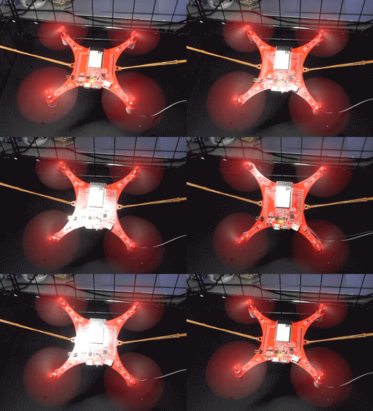
ゴムで吊るして動作確認しました。電源5Vは外部から供給しています。
割とよく姿勢制御ができています。
スマホのBlynkアプリからX軸の旋回とZ軸の回転を試してみました。
おわりに
姿勢制御の方針が決まり動作も確認できました。
以降はホバリング飛行を目指して調整進めていきたいと思います。
それでは次の道で!

