Micro OLED Display Test Using Visuino
 お父ちゃん
2017.3.16
お父ちゃん
2017.3.16
本記事にはアフィリエイト広告が含まれます。
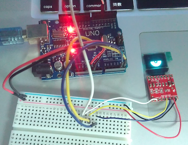
I tried animating the eye of a bitmap image using the Micro OLED module and Visuino.
目次
Configuration
Parts
- Microcomputer Arduino uno
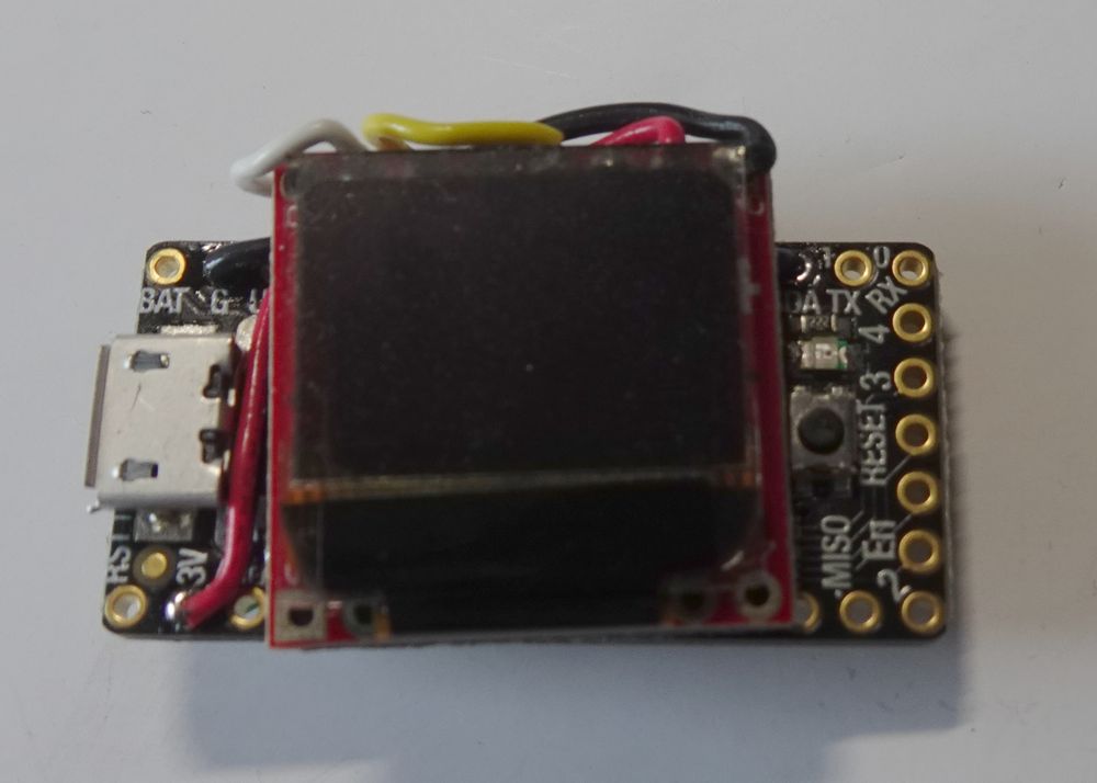
- SparkFun Micro OLED module
Setting the SparkFun Micro OLED module
This module has 64×48 pixels OLED screen and an SPI or I2C interface. Details are below:
Various settings are possible by connecting the jumper on the board.
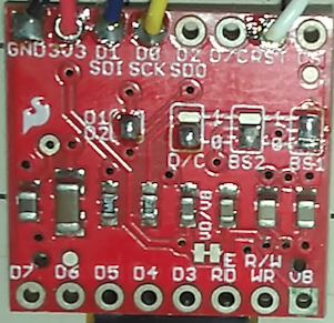
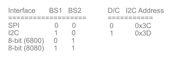
I set the communication method to I2C (BS1: 1, BS2: 0) and the I2C address to 0x3C (D/C: 0).
Setting the Visuino
Connect Arduino with OLED module to PC with USB and start Visuino.

Arduino Uno components are deployed when Visuino starts up. To change the type of microcomputer click on the tool icon and select the microcomputer. Select the COM of the microcontroller connected at [Port:].
Placement and wiring of SSD 1306 components
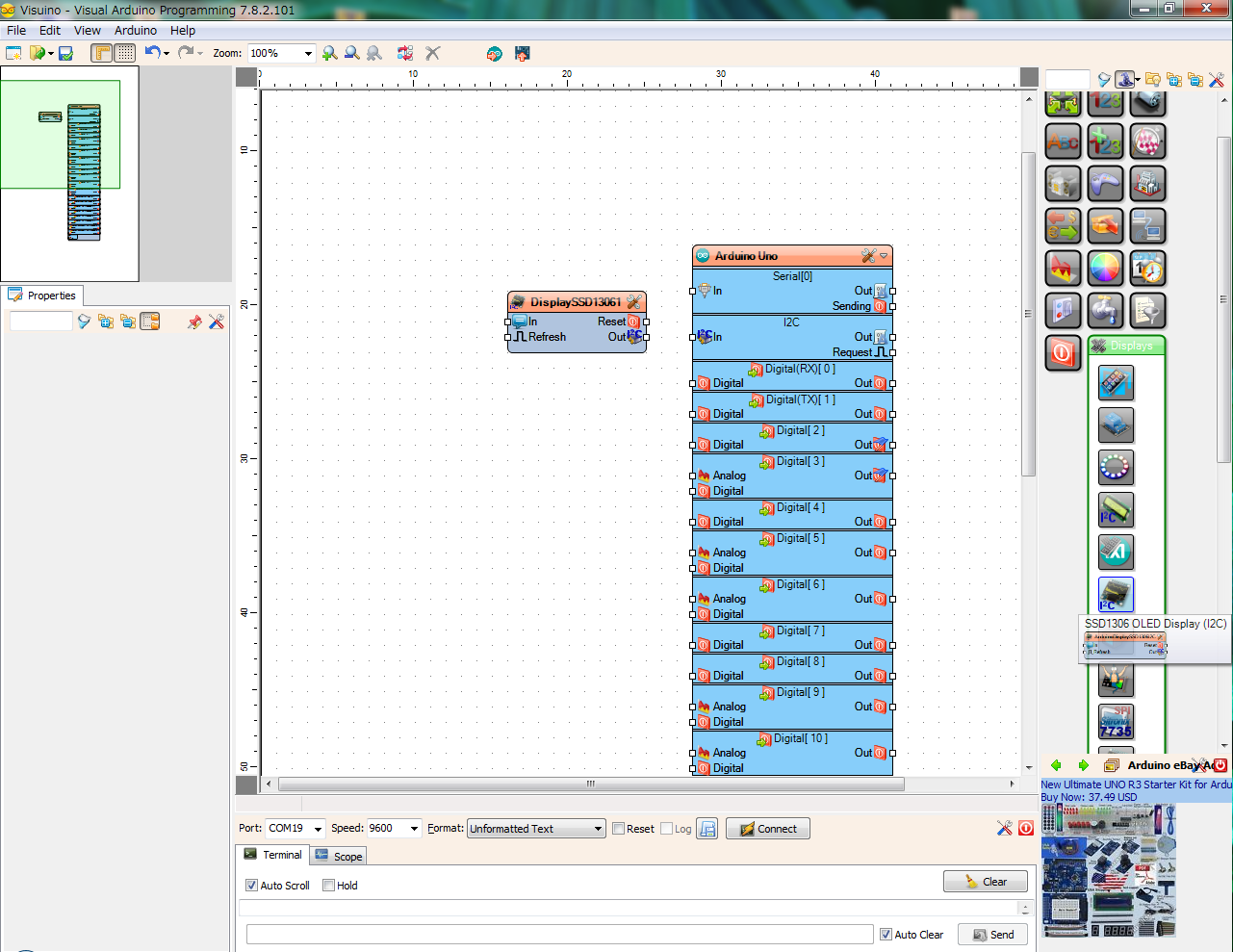
Select the component on the right side Window [Displays] – [SSD 1306 OLED Display (I2C)] and place it.

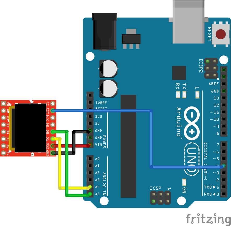
onnect Reset of SSD1306 component to Arduino’s D4 pin and I2C Out to I2C In.
Bitmap Image Settings
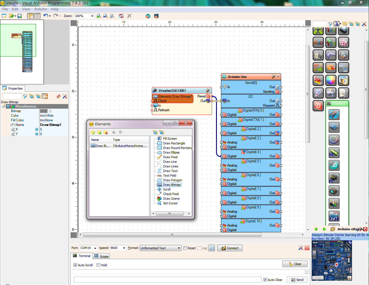
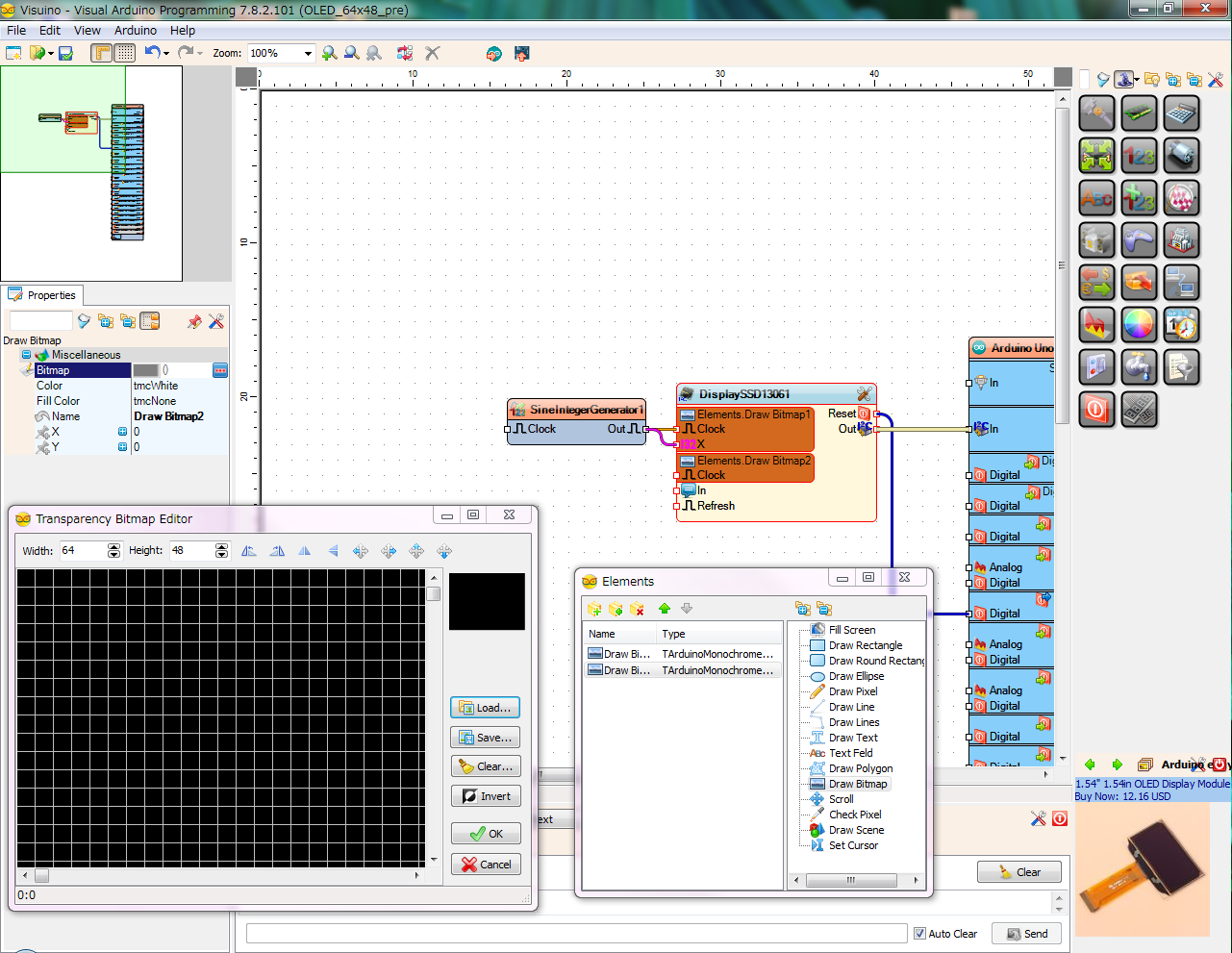
Double-click the SSD1306 component to open the Elements window. Double click on Draw Bitmap in the Elements window so that bitmap image can be handled with SSD1306.
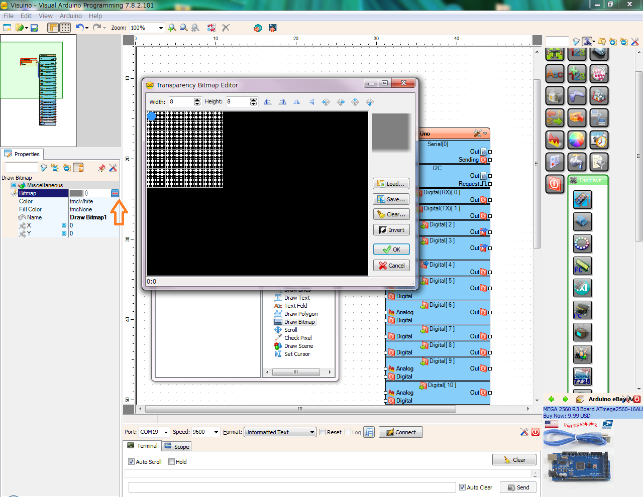
Select the Draw Bitmap, click […] in Bitmap in the Properties window on the right to open Transparency Bitmap Editor.
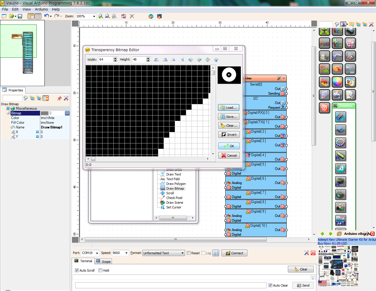
Click [Load] in the Transparency Bitmap Editor and load the picture of the eyeball created with 64 x 48 pixels.

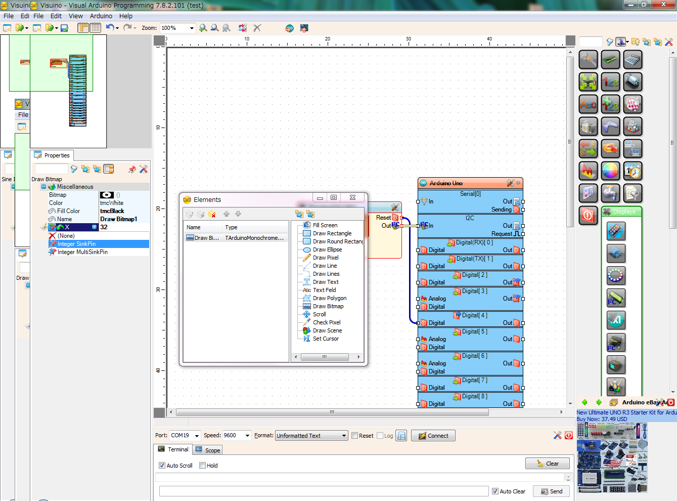
Select “tmcBlack” as the fill color in the Property window, enter 32 in X and 20 in Y so that eyeballs are displayed centrally. Also click on the thumbtack icon on the left of X to select Integer SinkPin so that X value can be entered externally.
Setting the Animation of image (X axis movement)
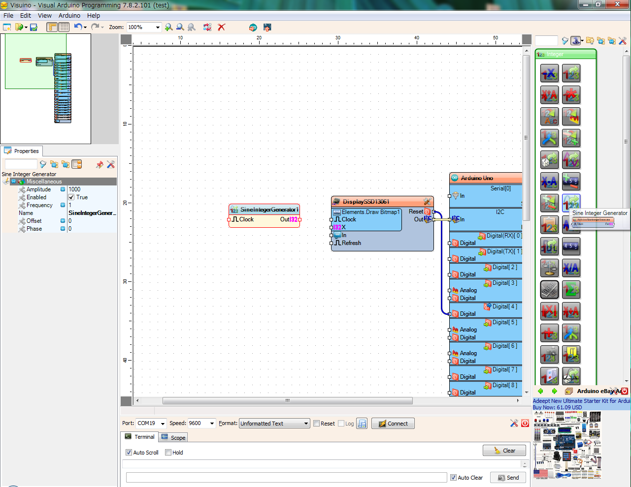
Select the component window on the right side [Integer] – [Sine Integer Generator] and place it.
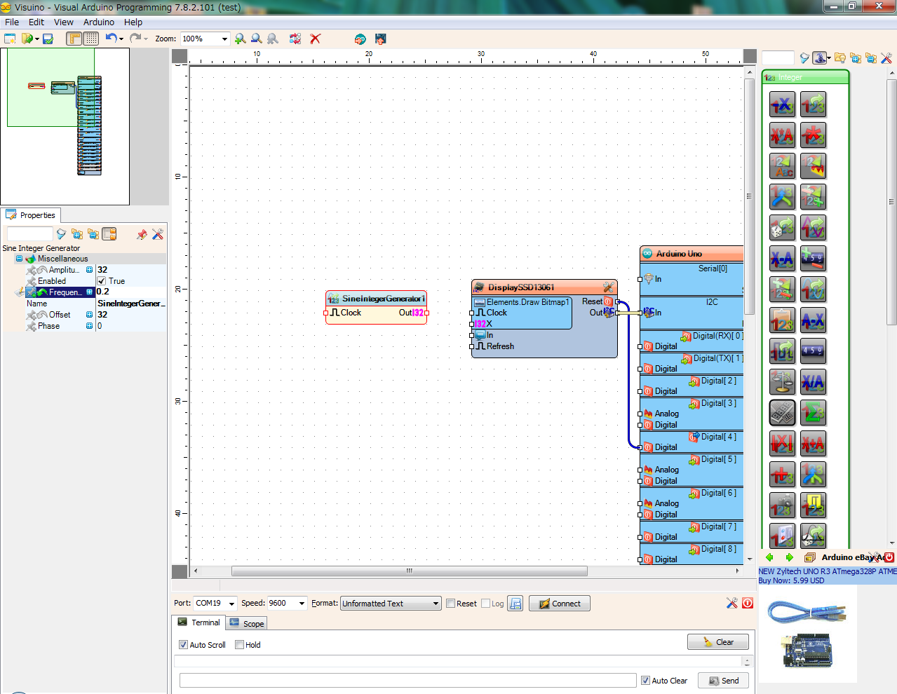
Select Sine Integer Generator component, enter 32 in Amplitude, 32 in Offset and 0.2 in Frequency in the Properties window.
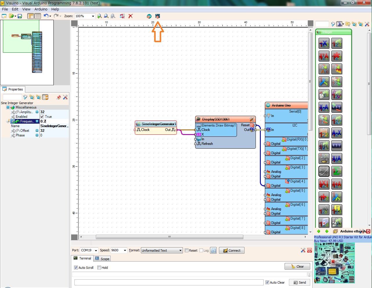
Connect Out of Sine Integer Generator component to Clock and X of SSD1306 component. The program is written to the microcomputer by clicking the [Send to Arduino]. With Position of the bitmap image changes with the integer (0 to 64) generated by the sine wave, then the eyeball moves in the X axis.
Add eyelid
Double-click the SSD1306 component to open the Elements window. Double click the Draw Bitmap in the Elements window and load the eyelid image as well as the eyeball.
Eyelids are 64 x 48 pixels all black image.

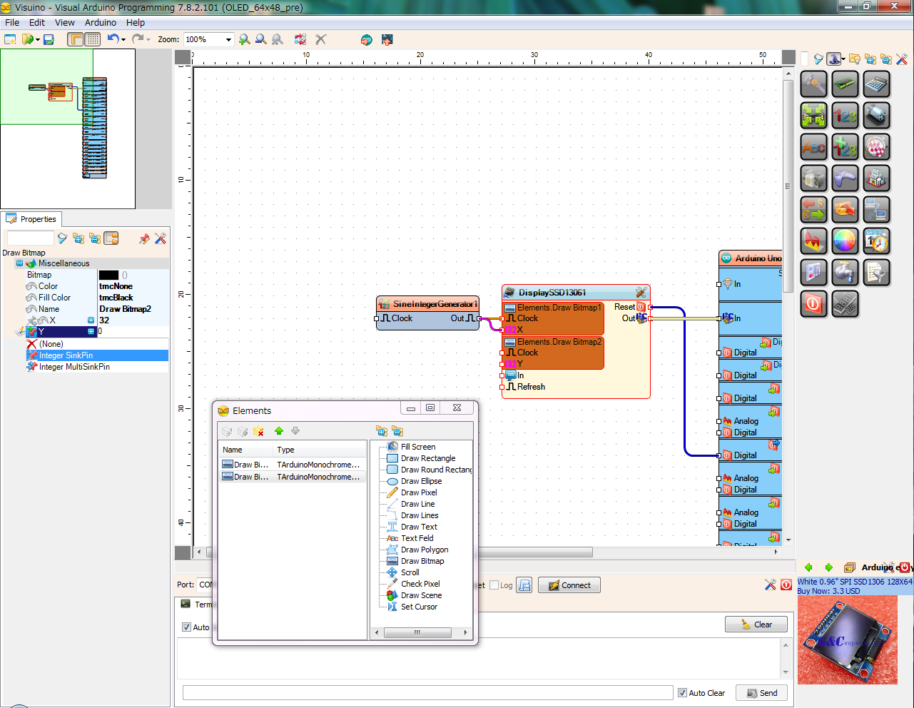
Select “tmcNon” for Color in the Properties window of eyelid image and “tmcBlack” for Fill Color and enter 32 for X Also click on the thumbtack icon on the left of Y to select Integer SinkPin so that Y value can be entered externally.

Place the Sine Integer Generator component as well as the eyeball, enter 24 in Amplitude, -4 in Offset and 0.4 in Frequency in the Properties window Connect the Out of the Sine Integer Generator component to Clock and Y of the eyelid bitmap within the SSD1306 component.
You can easily create an image animation with visual programming software Visuino!This is going to be a pretty hard task in an ordinary Arduino IDE…
Frequency of use of Visuino is likely to increase in the future!