新型コロナウイルス接触確認アプリ COCOAカウンター を Leafonyで作製
本記事にはアフィリエイト広告が含まれます。
厚生労働省が提供する、新型コロナ陽性登録した人との接触を知らせてくれるアプリ COCOA の周辺での起動数をカウントするデバイスを先日いただいた Leafony で製作しました。
目次
COCOAカウンター
COCOAはBLEのアドバタイズを検出してペアリングなしに接触を判定しているようです。
ミクミンPさんがM5ATOM LiteでCOCOAの起動を判定できるアプリを作製されたのをきっかけに
様々なCOCOAアプリカウンターがうまれました。
M5ATOM で接触確認アプリが有効かどうかを調べるやつをつくった。有効だと素早く点滅する。モバイルバッテリーで動作。 pic.twitter.com/aOdHc8Z5B6
— ミクミンP/Kazuhiro Sasao (@ksasao) June 20, 2020
- M5ATOM Matrixを用いたカウンター
ミクミンPさんのソースコード改変して近くに接触確認アプリが何個あるか表示できたよー
強度関係なしに特定のUUIDが何個あるか数えてるだけです pic.twitter.com/tLxZQAUtZB
— もけ@ムギ㌠ (@coppercele) June 21, 2020
- M5StickCを用いたカウンター
#接触確認アプリ #COCOA #M5StickC@coppercele さんの下記のQiita記事を参考にさせていただき、BLEで周囲のCOCOAアプリを検知し台数を表示するCOCOA Finderを作成してみた。地方ということもあり、人混みでもあまりカウント上がらない。https://t.co/oInPFuMENX pic.twitter.com/fPwLnxLoHG
— Google Homer (@google_homer_) June 29, 2020
Leafony COCOAカウンターの作製
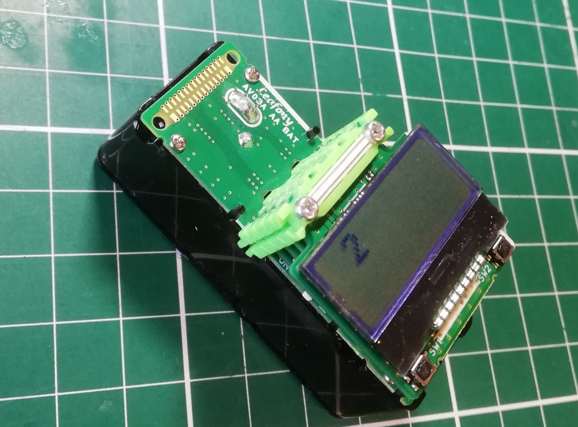
以下のLeafを用いてCOCOAカウンターを製作してみました。
- LCD Leaf (Extension Kit A1.0)
- BLE通信Leaf (Basic Kit A1.0)
- USBシリアルLeaf (Basic Kit A1.0)
- AVR MCU Leaf (Basic Kit A1.0)
- 単三電池Leaf (Extension Kit A1.0)
BLE通信LeafでCOCOAアプリを検出してLCDディスプレイLeafに検出したアプリ数を表示します。
Arduinoコード
BLE通信Leaf の仕様書とライブラリを参考にコーディングしました。
|
1 2 3 4 5 6 7 8 9 10 11 12 13 14 15 16 17 18 19 20 21 22 23 24 25 26 27 28 29 30 31 32 33 34 35 36 37 38 39 40 41 42 43 44 45 46 47 48 49 50 51 52 53 54 55 56 57 58 59 60 61 62 63 64 65 66 67 68 69 70 71 72 73 74 75 76 77 78 79 80 81 82 83 84 85 86 87 88 89 90 91 92 93 94 95 96 97 98 99 100 101 102 103 104 105 106 107 108 109 110 111 112 113 114 115 116 117 118 119 120 121 122 123 124 125 126 127 128 129 130 131 132 133 134 135 136 137 138 139 140 141 142 143 144 145 146 147 148 149 150 151 152 153 154 155 156 157 158 159 160 161 162 163 164 165 166 167 168 169 170 171 172 173 174 175 176 177 178 179 180 181 182 183 184 185 186 187 188 189 190 191 192 193 194 195 196 197 198 199 200 201 202 203 204 205 206 207 208 209 210 211 212 213 214 215 216 217 218 219 220 221 222 223 224 225 226 227 228 229 230 231 232 233 234 235 236 237 238 239 240 241 242 243 244 245 246 247 248 249 250 251 252 253 254 255 256 257 258 259 260 261 262 263 264 265 266 267 268 269 270 271 272 273 274 275 276 277 278 279 280 281 282 283 284 285 286 287 288 289 290 291 292 293 294 295 296 297 298 299 300 301 302 303 304 305 306 307 308 309 310 311 312 313 314 315 316 317 318 319 320 321 322 323 324 325 326 327 328 329 330 331 332 333 334 335 336 337 338 339 340 341 342 343 344 345 346 347 348 349 350 351 352 353 354 355 356 357 358 359 360 361 362 363 364 365 366 367 368 369 370 371 372 373 374 375 376 377 378 379 380 381 382 383 384 385 386 387 388 389 390 391 392 393 394 395 396 397 398 399 400 401 402 403 404 405 406 407 408 409 410 411 412 413 414 415 416 417 418 419 420 421 422 423 424 425 426 427 428 429 430 431 432 433 434 435 436 437 438 439 440 441 442 443 444 445 446 447 448 449 450 451 452 453 454 455 456 457 458 459 |
#include <MsTimer2.h> #include <Wire.h> #include "TBGLib.h" #include <SoftwareSerial.h> #include <ST7032.h> int cnt = 0; String term[20]; //===================================================================== // LCD出力 // LCD = 1 出力 LCD= 0出力無し // LCD出力を行う場合はST7032.hのインクルードを有効にすること //===================================================================== #define LCD (1) // LCD Leaf use:1 //===================================================================== // IOピンの名前定義 // 接続するリーフに合わせて定義する //===================================================================== // -------------------------------------------- // PD port // digital 0: PD0 = PCRX (HW UART) // digital 1: PD1 = PCTX (HW UART) // digital 2: PD2 = INT0# // digital 3: PD3 = INT1# // digital 4: PD4 = RSV // digital 5: PD5 = CN3_D5 // digital 6: PD6 = DISCN // digital 7: PD7 = BLSLP# // -------------------------------------------- #define PCTX 0 #define PCRX 1 #define INT0 2 #define INT1 3 #define LED 4 #define PIN3_D5 5 #define BLE_RESET_PIN 6 #define BLE_WAKEUP_PIN 7 // -------------------------------------------- // PB port // digital 8: PB0 = UART2_RX (software UART) /* not use */ // digital 9: PB1 = UART2_TX (software UART) /* not use */ // digital 10:PB2 = SS# // digital 11:PB3 = MOSI // digital 12:PB4 = MISO // digital 13:PB5 = SCK (LED) // PB6 = XTAL1 // PB7 = XTAL2 //--------------------------------------------- #define UART2_RX 8 #define UART2_TX 9 #define SS 10 #define MOSI 11 #define MISO 12 #define LED_PIN 13 // -------------------------------------------- // PC port // digital 14/ Analog0: PC0 = PIN24_D14 // digital 15/ Analog1: PC1 = BLETX (software UART) // digital 16/ Analog2: PC2 = BLERX (software UART) // digital 17/ Analog3: PC3 = PIN27_D17 // digital 18/ SDA : PC4 = SDA (I2C) // digital 19/ SCL : PC5 = SCL (I2C) // RESET : PC6 = RESET# //----------------------------------------------- #define PIN24_D14 14 #define BLETX 15 #define BLERX 16 #define PIN27_D17 17 #define SDA 18 #define SCL 19 //===================================================================== // プログラム内で使用する定数定義 // //===================================================================== //----------------------------------------------- //LCD I2Cアドレス //----------------------------------------------- #define I2C_EXPANDER_ADDR_LCD 0x1A //----------------------------------------------- // loop() interval // MsTimer2のタイマー割り込み発生間隔(ms) //----------------------------------------------- #define LOOP_INTERVAL 125 // 125ms interval //----------------------------------------------- // BLE //----------------------------------------------- #define BLE_STATE_STANDBY (0) #define BLE_STATE_SCANNING (1) #define BLE_STATE_ADVERTISING (2) #define BLE_STATE_CONNECTING (3) #define BLE_STATE_CONNECTED_MASTER (4) #define BLE_STATE_CONNECTED_SLAVE (5) //----------------------------------------------- // Batt ADC ADC081C027 //----------------------------------------------- #define BATT_ADC_ADDR 0x50 //----------------------------------------------- // BLE //----------------------------------------------- SoftwareSerial Serialble(BLERX, BLETX); BGLib ble112((HardwareSerial *)&Serialble, 0, 0 ); //----------------------------------------------- // LCD //----------------------------------------------- #if LCD ST7032 lcd; #endif //===================================================================== // プログラムで使用する変数定義 // //===================================================================== //===================================================================== // RAM data //===================================================================== //--------------------------- // loop counter //--------------------------- uint8_t iLoop1s = 0; uint8_t iSleepCounter = 0; uint8_t iSendCounter = 0; //--------------------------- // event //--------------------------- bool eventSensorRead = false; bool eventBLEsendData = false; bool eventSleepCheck = false; //--------------------------- // interval Timer2 interrupt //--------------------------- volatile bool bInterval = false; //--------------------------- // BLE //--------------------------- bool bBLEconnect = false; bool bBLEsendData = false; int8_t bleSendCount = 0; volatile uint8_t ble_state = BLE_STATE_STANDBY; volatile uint8_t ble_encrypted = 0; // 0 = not encrypted, otherwise = encrypted volatile uint8_t ble_bonding = 0xFF; // 0xFF = no bonding, otherwise = bonding handle //--------------------------- // LCD //--------------------------- volatile bool bLCDchange = false; volatile int lcd_view_sts = 0; //--------------------------- // Sleep, Watchdog Timer //--------------------------- volatile bool bSleep = false; volatile bool bBLESleep = false; volatile int countWDT = 0; volatile bool bWakeupINT0 = false; volatile bool bWakeupINT1 = false; //--------------------------- // led //--------------------------- uint8_t iLed = 0; volatile uint8_t iToggle = 8; bool bToggle = 0; //--------------------------- // Batt //--------------------------- float dataBatt = 0; //===================================================================== // setup //===================================================================== //----------------------------------------------- // port //----------------------------------------------- //===================================================================== // IOピンの入出力設定 // 接続するリーフに合わせて設定する //===================================================================== void setupPort(){ //--------------------- // PD port //--------------------- // PD0 : digital 0 = RX // PD1 : digital 1 = TX pinMode(INT0, INPUT); // PD2 : digital 2 = BLE interrupt pinMode(INT1, INPUT); // PD3 : digital 3 = sensor interrupt pinMode(LED, OUTPUT); // PD4 : digital 4 = LED digitalWrite(LED, LOW); pinMode(PIN3_D5, INPUT); // PD5 : digital 5 = not used pinMode(BLE_RESET_PIN, OUTPUT); // PD6 : digital 6 = BLE reset active-low digitalWrite(BLE_RESET_PIN, LOW); pinMode(BLE_WAKEUP_PIN, OUTPUT); // PD7 : digital 7 = BLE sleep digitalWrite(BLE_WAKEUP_PIN, HIGH); //--------------------- // PB port //--------------------- pinMode(UART2_RX, INPUT); // PB0 : digital 8 = software UART2 pinMode(UART2_TX, INPUT); // PB1 : digital 9 = software UART2 pinMode(SS, INPUT); // PB2 : digital 10 = not used pinMode(MOSI, INPUT); // PB3 : digital 11 = not used pinMode(MISO, INPUT); // PB4 : digital 12 = not used pinMode(LED_PIN, OUTPUT); // PB5 : digital 13 =LED on 8bit-Dev. Leaf digitalWrite(LED_PIN, LOW); //--------------------- // PC port //--------------------- pinMode(PIN24_D14, INPUT); // PC0 : digital 14 = not used // PC1 : digital 15 = BLETX // PC2 : digital 16 = BLERX pinMode(PIN27_D17, INPUT); // PC3 : digital 17 = not used // PC4 : digital 18 = I2C SDA // PC5 : digital 19 = I2C SCL } //===================================================================== // 割り込み処理初期設定 // //===================================================================== //----------------------------------------------- // external interrupt // 外部割り込み設定 //----------------------------------------------- void setupExtInt(){ attachInterrupt(0, intExtInt0, FALLING); // BLE INT0# = enabled detachInterrupt(1); // sensor INT1# = disabled } //----------------------------------------------- // timer2 interrupt (interval=125ms, int=overflow) // メインループのタイマー割り込み設定 //----------------------------------------------- void setupTC2Int(){ MsTimer2::set(LOOP_INTERVAL, intTimer2); } //===================================================================== // I2C 制御関数 // //===================================================================== //----------------------------------------------- //I2C スレーブデバイスに1バイト書き込む //----------------------------------------------- void i2c_write_byte(int device_address, int reg_address, int write_data){ Wire.beginTransmission(device_address); Wire.write(reg_address); Wire.write(write_data); Wire.endTransmission(); } //----------------------------------------------- //I2C スレーブデバイスから1バイト読み込む //----------------------------------------------- unsigned char i2c_read_byte(int device_address, int reg_address){ int read_data = 0; Wire.beginTransmission(device_address); Wire.write(reg_address); Wire.endTransmission(false); Wire.requestFrom(device_address, 1); read_data = Wire.read(); return read_data; } //---------------------------------------------- // Timer2 INT // タイマー割り込み関数 //---------------------------------------------- void intTimer2(){ bInterval = 1; } //---------------------------------------------- // INT0 // INT0割り込み関数 //---------------------------------------------- void intExtInt0(){ bSleep = false; //bWakeupINT0 = true; } //-------------------------------------------------------------------- // BLE //-------------------------------------------------------------------- //----------------------------------------- // main loop // BLEからデータが送信されていたらデータを取得し、取得データに従い // 処理を実施 //----------------------------------------- void loopBleRcv( void ){ // keep polling for new data from BLE ble112.checkActivity(0); /* 受信チェック */ /* */ if (ble_state == BLE_STATE_STANDBY) { bBLEconnect = false; /* [BLE] 接続状態 */ } else if (ble_state == BLE_STATE_ADVERTISING) { bBLEconnect = false; /* [BLE] 接続状態 */ } else if (ble_state == BLE_STATE_CONNECTED_SLAVE) { /* */ bBLEconnect = true; /* [BLE] 接続状態 */ /* */ if (!ble_encrypted) { // digitalWrite(LED_PIN, slice < 100 || (slice > 200 && slice < 300)); } else { // digitalWrite(LED_PIN, slice < 100 || (slice > 200 && slice < 300) || (slice > 400 && slice < 500)); } } } //==================================================================== // setup //==================================================================== void setup() { Serial.begin(115200); Serial.println("setup!!!"); Wire.begin(); // I2C 100KHz i2c_write_byte(I2C_EXPANDER_ADDR_LCD, 0x03, 0xFE); i2c_write_byte(I2C_EXPANDER_ADDR_LCD, 0x01, 0x01); lcd.begin(8, 2); lcd.setContrast(30); lcd.clear(); lcd.setCursor(1, 0); lcd.print("0"); setupPort(); delay(10); noInterrupts(); setupTC2Int(); interrupts(); //スキャン応答を受信した時に呼ばれるコールバック ble112.ble_evt_le_gap_scan_response = my_evt_le_gap_scan_response; Serialble.begin(9600); //Bluetooth discovery mode 設定 ble112.ble_cmd_le_gap_discover(2); while (ble112.checkActivity(1000)); delay(1000); MsTimer2::start(); // Timer2 inverval start } //==================================================================== // loop //==================================================================== void loop() { //----------------------------------------------------- // Timer2 interval 125ms で1回ループ //----------------------------------------------------- if (bInterval == true){ bInterval = false; } loopBleRcv(); } //スキャン応答 void my_evt_le_gap_scan_response(const struct ble_msg_le_gap_scan_response_evt_t *msg ){ //struct ble_msg_le_gap_scan_response_evt_t { // int8 rssi; /* [4] */ // uint8 packet_type; /* [5] */ // bd_addr sender; /* [6~11] */ // uint8 address_type; /* [12] */ // uint8 bond; /* [13] */ // uint8array data; /* [14] */ //} __attribute__((packed)); uint8 data_len = msg -> data.len; String rcv_data = ""; for (uint8_t i = 1; i <= data_len; i++) { rcv_data += String(msg -> data.data[data_len - i], HEX); } String rcv_sender = ""; for (int i = 0; i < 6 ;i++){ rcv_sender += String(msg->sender.addr[i], HEX); } if(rcv_data.indexOf("fd6f1617fd6f33") > 30 && rcv_data.length() < 70 && rcv_sender.length() > 10){ if(cnt == 0){ term[0] = rcv_sender; cnt++; lcd.clear(); lcd.setCursor(1, 0); lcd.print(cnt); }else{ int chk = 0; for(int i = 0; i < cnt; i++){ if(term[i] == rcv_sender){ chk = 1; } } if(chk == 0){ term[cnt] = rcv_sender; cnt++; lcd.clear(); lcd.setCursor(1, 0); lcd.print(cnt); } } Serial.print(cnt); Serial.print(" RSSI: "); Serial.print(msg->rssi,DEC); Serial.print( " address: " ); Serial.print(rcv_sender); Serial.print(" data: "); Serial.print(rcv_data); Serial.println(); } } |
L. 379:BLEデバイスをスキャンし応答があったときに呼ばれるコールバック関数ble_evt_le_gap_scan_responseでスキャン内容を取得します。
L. 384:Bluetooth discovery mode 設定
全てのデバイスを検出します。
L. 406-459:スキャンしたデバイス情報を取得しCOCOAアプリの場合はカウントします。
スキャンしたBLEアドバタイズからCOCOAのサービスUUIDを検出する方法は分からなかったのですが付与されるdataにそれっぽい値(0xFD6F)が入っていたので、この値でアプリを判別しています。
ああ、ちゃんと仕様書に書いてありますね。Contact Detection Service の UUID https://t.co/3Op0y6CVuw pic.twitter.com/Z7d1HEKAMI
— ミクミンP/Kazuhiro Sasao (@ksasao) June 20, 2020
↓検出したデバイスの様子 (シリアルモニタ)
動作
接触確認アプリの数を数えるヤツを真似して
Leafonyで作ってみた。#接触確認アプリ #COCOA #leafony pic.twitter.com/DCRECJdS7d— HomeMadeGarbage (@H0meMadeGarbage) July 24, 2020
近傍のCOCOAアプリを検出してカウントできることを確認いたしました。
単三電池Leaf によって電池一本で手軽に動かせます。←喜びポイント
今度外出時に携えて巷のCOCOAアプリの普及具合を体感してみたいと思います。
