ロボット犬『Mini Pupperミニぷぱ』Pythonでモーション記述
本記事にはアフィリエイト広告が含まれます。
前回はミニぷぱ正規の構成でラズパイ4にRaspi OSとNode-REDを導入して動作を確認いたしました。
ここでは、動作モーションを増やしてのコントロールを検討します。
目次
モーション制御検討
Python
前回はNode-REDで動作を仕込みましたが、複数のモーションになると煩雑になるためPythonを採用することにしました。
サーボドライバ PCA9685用のPythonライブラリは以下を使用しました。
https://github.com/adafruit/Adafruit_Python_PCA9685
ちなみにこのライブラリでも専用基板のサーボナンバー 1~12がPCA9685ノードの15~4に対応していました。基板上そういった接続なっているのかもしれません。
Node-RED Dashboard
ミニぷぱコントロールUIにはNode-RED-Dashboardを使用することにしました。
https://flows.nodered.org/node/node-red-dashboard
これによってブラウザ上のボタンなどで制御可能となります。
動作
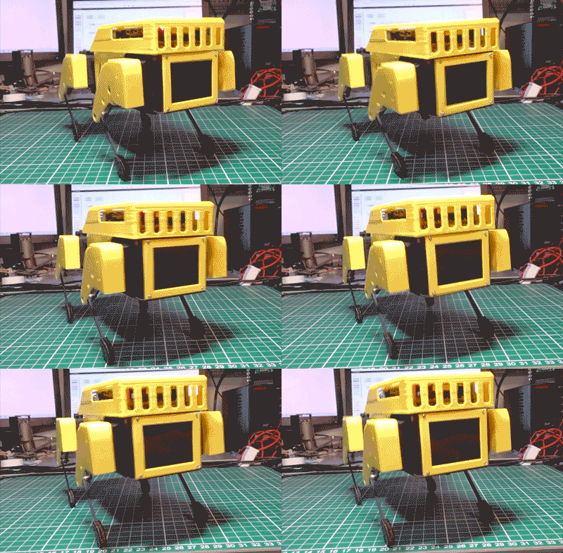
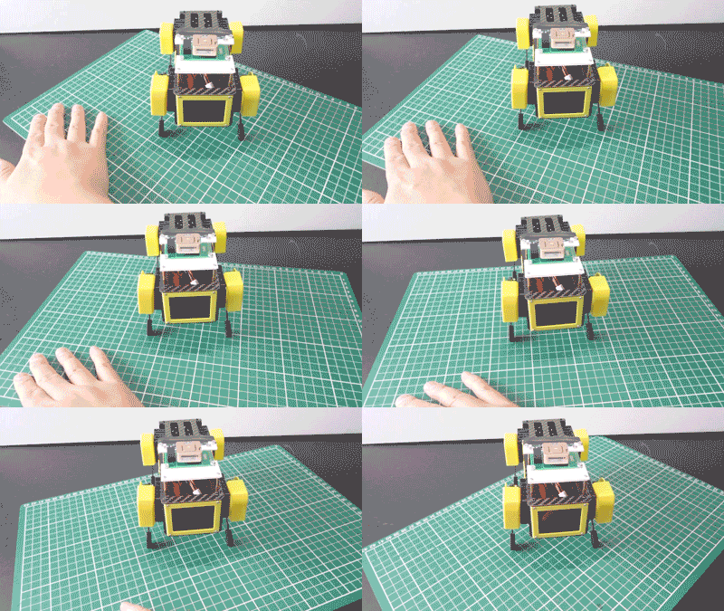
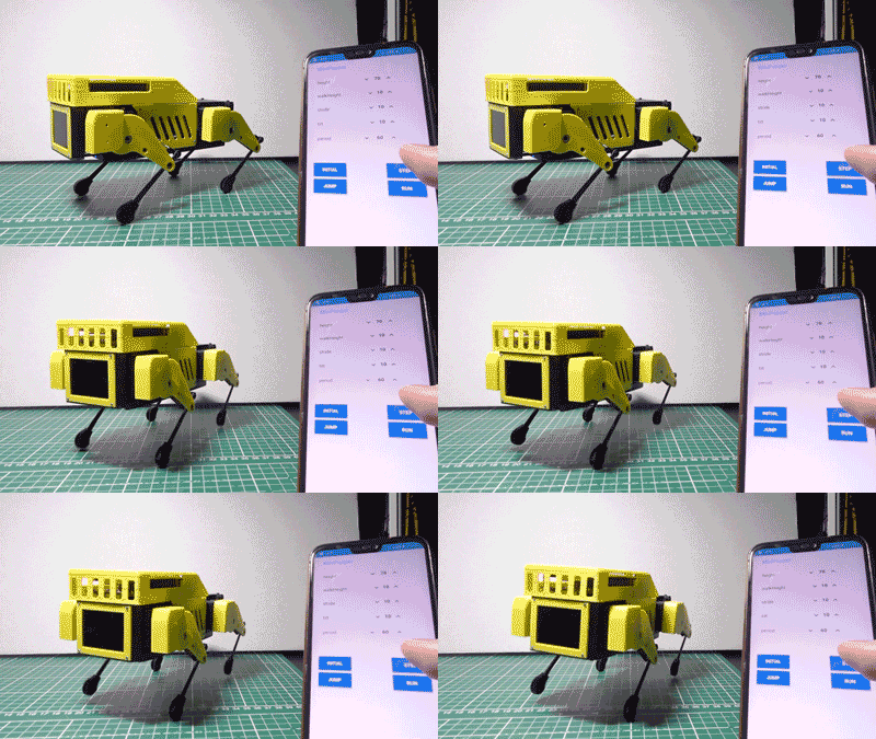
Node-RED-Dashboardのボタンで足の高さを指定しています。
ブラウザで動くのでスマホでもコントロールできます。
逆運動学によるモーションはpythonで書いて
UIはnode-red-dashboardにする
そうすればスマホでもコントロールできる#MiniPupper #ミニぷぱ #nodeRED #python pic.twitter.com/cFF8FWf7G0— HomeMadeGarbage (@H0meMadeGarbage) February 17, 2022
ミニぷぱモーション制御
Dashboard
Node-RED Dashboardのnumericノードで足の高さや上げ幅、歩幅などを指定します。
buttonノードで各種モーションを起動します。
モーションは初期姿勢、足踏み、ジャンプ、ランニングマンを用意しました。
Node-RED
Node-REDの構成は以下のとおり
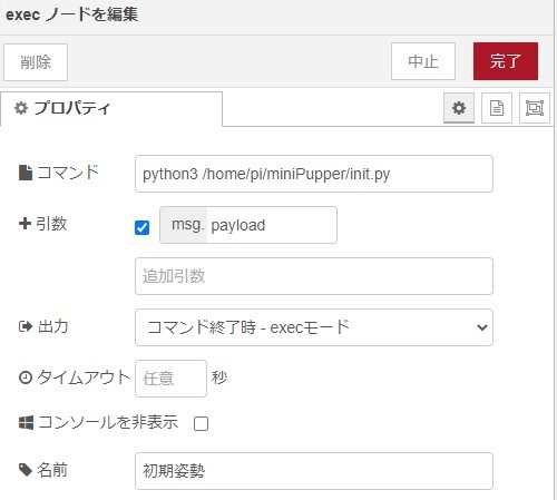
動作指定ボタンを受けて各モーションのPythonコードを起動しています。
Python起動時にnumericノードで指定したパラメータをmsg.payloadで引数として渡しています。
Pythonコード
足踏み動作は以下のような感じで
|
1 2 3 4 5 6 7 8 9 10 11 12 13 14 15 16 17 18 19 20 21 22 23 24 25 26 27 28 29 30 31 32 33 34 35 36 37 38 39 40 41 42 43 44 45 46 47 48 49 50 51 52 53 54 55 56 57 58 59 60 61 62 63 64 65 66 67 68 69 70 71 72 73 74 75 76 77 78 79 80 81 82 83 84 85 86 87 88 89 90 91 92 93 94 95 96 97 98 99 100 101 102 103 104 105 106 107 108 109 110 111 112 113 114 115 116 117 118 119 120 121 122 123 124 125 126 127 128 129 130 131 132 |
# Simple demo of of the PCA9685 PWM servo/LED controller library. # This will move channel 0 from min to max position repeatedly. # Author: Tony DiCola # License: Public Domain from __future__ import division import time import math import sys # Import the PCA9685 module. import Adafruit_PCA9685 args = sys.argv # Uncomment to enable debug output. #import logging #logging.basicConfig(level=logging.DEBUG) # Initialise the PCA9685 using the default address (0x40). pwm = Adafruit_PCA9685.PCA9685() # Alternatively specify a different address and/or bus: #pwm = Adafruit_PCA9685.PCA9685(address=0x41, busnum=2) # Configure min and max servo pulse lengths servo_min = 130 # Min pulse length out of 4096 servo_max = 640 # Max pulse length out of 4096 offset = [0, 78, 117, 36, 83, 36, 97, 78, 119, 35, 100, 69, 125] L1=50 L2=56 #rRz = int(args[1]) height = int(args[1]) walkHeight = int(args[2]) stride = int(args[3]) tilt = int(args[4]) period = int(args[5]) # Set frequency to 60hz, good for servos. pwm.set_pwm_freq(60) #servo control def servo_write(ch, ang): ang = int((servo_max - servo_min) / 180.0 * ang + servo_min) pwm.set_pwm(16 - ch, 0, ang) def fRIK(x, th0, z): zd = z / math.cos(th0/180.0 * math.pi) ld = math.sqrt(x*x + zd*zd) phi = math.atan2(x, zd) th1 = phi - math.acos((L1*L1 + ld*ld - L2*L2)/(2*L1*ld)) th2 = math.acos((ld*ld - L1*L1 - L2*L2)/(2*L1*L2)) + th1 servo_write(1, th0 + offset[1]); servo_write(2, th1 * 180.0 / math.pi + offset[2]); servo_write(3, th2 * 180.0 / math.pi + offset[3]); def rRIK(x, th0, z): zd = z / math.cos(th0/180.0 * math.pi) ld = math.sqrt(x*x + zd*zd) phi = math.atan2(x, zd) th1 = phi - math.acos((L1*L1 + ld*ld - L2*L2)/(2*L1*ld)) th2 = math.acos((ld*ld - L1*L1 - L2*L2)/(2*L1*L2)) + th1 servo_write(7, th0 + offset[7]); servo_write(8, th1 * 180.0 / math.pi + offset[8]); servo_write(9, th2 * 180.0 / math.pi + offset[9]); def fLIK(x, th0, z): zd = z / math.cos(th0/180.0 * math.pi) ld = math.sqrt(x*x + zd*zd) phi = math.atan2(x, zd) th1 = phi - math.acos((L1*L1 + ld*ld - L2*L2)/(2*L1*ld)) th2 = math.acos((ld*ld - L1*L1 - L2*L2)/(2*L1*L2)) + th1 servo_write(4, th0 + offset[4]); servo_write(5, -(th1 * 180.0 / math.pi) + offset[5]); servo_write(6, -(th2 * 180.0 / math.pi) + offset[6]); def rLIK(x, th0, z): zd = z / math.cos(th0/180.0 * math.pi) ld = math.sqrt(x*x + zd*zd) phi = math.atan2(x, zd) th1 = phi - math.acos((L1*L1 + ld*ld - L2*L2)/(2*L1*ld)) th2 = math.acos((ld*ld - L1*L1 - L2*L2)/(2*L1*L2)) + th1 servo_write(10, th0 + offset[10]); servo_write(11, -(th1 * 180.0 / math.pi) + offset[11]); servo_write(12, -(th2 * 180.0 / math.pi) + offset[12]); while True: time_mSt = time.time() * 1000 tim = 0 while tim < period: tim = time.time() * 1000 - time_mSt tt = tim * math.pi / 2.0 / period fRIK(0, 0, height - walkHeight * math.sin(tt)) rLIK(0, 0, height - walkHeight * math.sin(tt)) time_mSt = time.time() * 1000 tim = 0 while tim < period: tim = time.time() * 1000 - time_mSt tt = tim * math.pi / 2.0 / period fRIK(0, 0, height - walkHeight * math.cos(tt)) rLIK(0, 0, height - walkHeight * math.cos(tt)) time_mSt = time.time() * 1000 tim = 0 while tim < period: tim = time.time() * 1000 - time_mSt tt = tim * math.pi / 2.0 / period rRIK(0, 0, height - walkHeight * math.sin(tt)) fLIK(0, 0, height - walkHeight * math.sin(tt)) time_mSt = time.time() * 1000 tim = 0 while tim < period: tim = time.time() * 1000 - time_mSt tt = tim * math.pi / 2.0 / period rRIK(0, 0, height - walkHeight * math.cos(tt)) fLIK(0, 0, height - walkHeight * math.cos(tt)) |
参考
動作
足踏みやジャンプを仕込んで
いよいよ前後左右への歩行
dashboardにはジョイスティックがなく
ボタンやスライダじゃきついなぁと思った時
Blynkはラズパイもいけたことに気づく。。ラズパイ4に対応してるかは明日のおかずだな#MiniPupper #ミニぷぱ #nodeRED #python pic.twitter.com/ybpuc5jLUj
— HomeMadeGarbage (@H0meMadeGarbage) February 17, 2022
前後左右への歩行を仕込もうと思ったのですがdashboardにはジョイスティックがなくボタンやスライダじゃきついなぁと思った時に
Blynkはラズパイもいけたことに気づきました。。。
次はBlynkでの動作検証します。
おわりに
ここではNode-RED DashboardとPythonを用いてモーションコントロールを楽しみました。
しかしNode-RED DashboardのUIではリアルタイムラジコンを制御するには少し物足りない印象でした。
Blynkがラズパイ対応していたことに今さら気づいたので次回検証進めます!
追記 (ディスプレイ表示)
どうもラズパイ4はBlynkに対応されてないようなので、ラズパイを用いた本構成の検討はコレで一旦休止しようと思います。
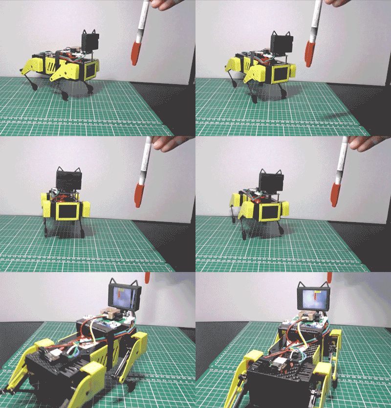
最後にせっかくなのでディスプレイ表示だけ確認しました。
ディスプレイには320×240ピクセルのST7789が使用されていることが以下で解ります。
SPIで制御されておりピン配もPythonコードから読み取ることができます。
https://github.com/mangdangroboticsclub/QuadrupedRobot/tree/MiniPupper_V2/Mangdang/LCD
ST7789制御
以下を参考にST7789用Python環境を構築しました。
またRaspiコンフィグでSPIを有効にします。
Pythonコード
上記を参考にして320×240のJPEG画像を表示するPythonコードをこしらえました。
|
1 2 3 4 5 6 7 8 9 10 11 12 13 14 15 16 17 18 19 |
import ST7789 from PIL import Image # Create a display instance disp = ST7789.ST7789(port=0, cs=0, rst=27, dc=24, backlight=26, width=320, height=240, rotation=180, spi_speed_hz=40 * 1000 * 1000) # Added: Change to SPI MODE 3 disp._spi.mode = 3 disp.reset() disp._init() # Open image file image = Image.open("L.jpg") # Resize to screen size image = image.resize((320, 240)) # Show it on display disp.display(image) |
動作
ディスプレイ表示できるように なたよ#MiniPupper #ミニぷぱ #ST7789 #python #ペットボトル pic.twitter.com/8aJwefMM3A
— HomeMadeGarbage (@H0meMadeGarbage) February 18, 2022
表示できました!
思えばラズパイにLCDつないでSPIで制御したの初めてかも
勉強になりました!


