M5StickC で倒立振子 Blynk でコントロール ー倒立振子への道 4ー
本記事にはアフィリエイト広告が含まれます。
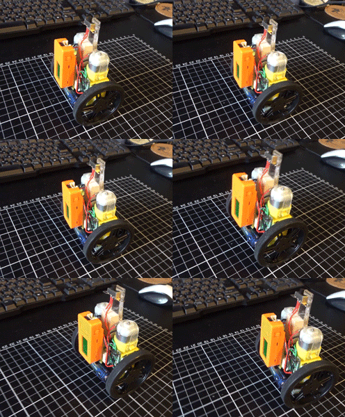
前回、実現できたM5StickCによる倒立振子を前進/後進/旋回動作できるようにいたしました。
倒立振子自体の制御は前回と同様にPID制御です。タイヤの回転などを加味したより安定した制御方法は現在勉強中です。いつまでかかるかな。。。?
目次
動作
早速動作を見てください。
制御可能となった。うれしい。#M5StickC #Blynk #倒立振子への道
BGM by Welcome脳https://t.co/Y33WdIluJx pic.twitter.com/Rb5D7EpUHp
— HomeMadeGarbage (@H0meMadeGarbage) 2019年7月15日
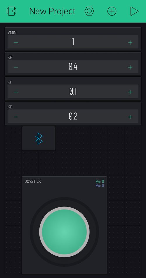
スマホアプリBlynkを使用してBluetoothでコントロールしています。なかなかかわいいです♪
Blynk設定
前回のアプリ設定にジョイスティックウィジットを追加しただけです。
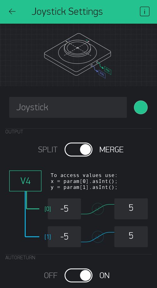
ジョイスティックの設定はx軸とy軸の出力をMERGEしてヴァーチャルピンV4に出力させ、それぞれ値は-5~5としました。y軸の値で前進/後進をx軸で左右旋回動作します。値が大きくなるほど動作速度が上がります。
Arduino IDEプログラム
前回とほぼ同様のコードです。カルマン・フィルタによって傾斜角と角速度の推定値を導出してPID制御によってモータをフィードバック制御しております。
|
1 2 3 4 5 6 7 8 9 10 11 12 13 14 15 16 17 18 19 20 21 22 23 24 25 26 27 28 29 30 31 32 33 34 35 36 37 38 39 40 41 42 43 44 45 46 47 48 49 50 51 52 53 54 55 56 57 58 59 60 61 62 63 64 65 66 67 68 69 70 71 72 73 74 75 76 77 78 79 80 81 82 83 84 85 86 87 88 89 90 91 92 93 94 95 96 97 98 99 100 101 102 103 104 105 106 107 108 109 110 111 112 113 114 115 116 117 118 119 120 121 122 123 124 125 126 127 128 129 130 131 132 133 134 135 136 137 138 139 140 141 142 143 144 145 146 147 148 149 150 151 152 153 154 155 156 157 158 159 160 161 162 163 164 165 166 167 168 169 170 171 172 173 174 175 176 177 178 179 180 181 182 183 184 185 186 187 188 189 190 191 192 193 194 195 196 197 198 199 200 201 202 203 204 205 206 207 208 209 210 211 212 213 214 215 216 217 218 219 220 221 222 223 224 225 226 227 228 229 230 231 232 233 234 235 236 237 238 239 240 241 242 243 244 245 246 247 248 249 250 251 252 253 254 255 256 257 258 259 260 261 262 263 264 265 266 267 268 269 270 271 272 273 274 275 276 277 278 279 280 281 282 283 284 285 286 287 288 289 290 291 292 293 294 295 296 297 298 299 300 301 302 303 304 305 306 307 308 309 310 311 312 313 314 315 316 317 318 319 320 321 322 323 324 325 326 327 328 329 330 331 332 333 334 335 336 337 338 339 340 341 342 343 344 345 346 347 348 349 350 351 352 353 354 355 356 357 358 359 360 361 362 363 364 365 366 367 368 369 370 371 372 373 374 375 376 377 378 379 380 381 382 383 384 385 386 387 388 389 390 391 392 393 394 395 396 397 398 399 400 401 402 403 404 405 406 407 408 409 410 411 412 413 414 415 416 417 418 419 420 421 422 423 424 425 426 427 428 429 430 431 432 433 434 435 436 437 438 439 440 441 442 443 444 445 446 447 448 449 450 451 452 453 454 455 456 457 458 459 460 461 462 463 464 465 466 467 468 469 470 471 472 473 474 475 476 477 478 479 480 481 482 483 484 485 486 487 488 489 490 491 492 493 494 495 496 497 498 499 500 501 502 503 504 505 506 507 508 509 510 511 512 513 514 515 516 517 518 519 520 521 522 523 524 525 526 527 528 529 530 531 532 533 534 535 536 537 538 539 540 541 542 543 544 545 546 547 548 549 550 551 552 553 554 555 |
#define BLYNK_PRINT Serial #define BLYNK_USE_DIRECT_CONNECT #include <BlynkSimpleEsp32_BT.h> #include <M5StickC.h> #include <Ticker.h> #include <Wire.h> char auth[] = "BlynkアプリのYourAuthTokenを入力"; int VMIN = 1; float Kp = 0.4; float Ki = 0.1; float Kd = 0.2; int mXL = 0, mXR = 0, mY = 0; float powerL = 0.0, powerR = 0.0; float thetaLP, thetaRP, thetaLI, thetaRI, thetaD; #define WAIT 10 #define VMAX 63 int16_t accX = 0; int16_t accY = 0; int16_t accZ = 0; int16_t gyroX = 0; int16_t gyroY = 0; int16_t gyroZ = 0; //加速度センサ オフセット int accXoffset = 0; int accYoffset = 0; int accZoffset = 0; //ジャイロセンサ オフセット int gyroXoffset = 0; int gyroYoffset = 0; int gyroZoffset = 0; Ticker tickerUpdate; //センサ バラつき取得用変数 int sample_num = 100; int meas_interval = 10; float theta_deg = 0.0; float theta_dot = 0.0; float theta_dot2; float theta_mean; float theta_variance; float theta_dot_mean; float theta_dot_variance; //========================================================= //カルマン・フィルタ用変数 //========================================================= //カルマン・フィルタ処理 float theta_update_freq = 400; //Hz float theta_update_interval = 1.0/double(theta_update_freq); //2.5msec //状態ベクトルx //[[theta(degree)], [offset of theta_dot(degree/sec)]] //状態ベクトルの予測値 float theta_data_predict[2][1]; float theta_data[2][1]; //共分散行列 float P_theta_predict[2][2]; float P_theta[2][2]; //状態方程式の"A" float A_theta[2][2] = {{1, -theta_update_interval}, {0, 1}}; //状態方程式の"B" float B_theta[2][1] = {{theta_update_interval}, {0}}; //出力方程式の"C" float C_theta[1][2] = {{1, 0}}; //========================================================= // 行列演算関数 //========================================================= //行列の和 void mat_add(float *m1, float *m2, float *sol, int row, int column) { for(int i=0; i<row; i++) { for(int j=0; j<column; j++) { sol[i*column + j] = m1[i*column + j] + m2[i*column + j]; } } return; } //行列の差 void mat_sub(float *m1, float *m2, float *sol, int row, int column){ for(int i=0; i<row; i++) { for(int j=0; j<column; j++) { sol[i*column + j] = m1[i*column + j] - m2[i*column + j]; } } return; } //行列の積 void mat_mul(float *m1, float *m2, float *sol, int row1, int column1, int row2, int column2){ for(int i=0; i<row1; i++){ for(int j=0; j<column2; j++){ sol[i*column2 + j] = 0; for(int k=0; k<column1; k++) { sol[i*column2 + j] += m1[i*column1 + k]*m2[k*column2 + j]; } } } return; } //転置行列算出 void mat_tran(float *m1, float *sol, int row_original, int column_original) { for(int i=0; i<row_original; i++) { for(int j=0; j<column_original; j++) { sol[j*row_original + i] = m1[i*column_original + j]; } } return; } //行列の定数倍算出 void mat_mul_const(float *m1,float c, float *sol, int row, int column){ for(int i=0; i<row; i++){ for(int j=0; j<column; j++){ sol[i*column + j] = c * m1[i*column + j]; } } return; } //逆行列算出 void mat_inv(float *m, float *sol, int column, int row){ //allocate memory for a temporary matrix float* temp = (float *)malloc( column*2*row*sizeof(float) ); //make the augmented matrix for(int i=0; i<column; i++) { //copy original matrix for(int j=0; j<row; j++) { temp[i*(2*row) + j] = m[i*row + j]; } //make identity matrix for(int j=row; j<row*2; j++) { if(j-row == i) { temp[i*(2*row) + j] = 1; } else { temp[i*(2*row) + j] = 0; } } } //Sweep (down) for(int i=0; i<column; i++) { //pivot selection float pivot = temp[i*(2*row) + i]; int pivot_index = i; float pivot_temp; for(int j=i; j<column;j++) { if( temp[j*(2*row)+i] > pivot ) { pivot = temp[j*(2*row) + i]; pivot_index = j; } } if(pivot_index != i) { for(int j=0; j<2*row; j++) { pivot_temp = temp[ pivot_index * (2*row) + j ]; temp[pivot_index * (2*row) + j] = temp[i*(2*row) + j]; temp[i*(2*row) + j] = pivot_temp; } } //division for(int j=0; j<2*row; j++) { temp[i*(2*row) + j] /= pivot; } //sweep for(int j=i+1; j<column; j++) { float temp2 = temp[j*(2*row) + i]; //sweep each row for(int k=0; k<row*2; k++) { temp[j*(2*row) + k] -= temp2 * temp[ i*(2*row) + k ]; } } } //Sweep (up) for(int i=0; i<column-1; i++) { for(int j=i+1; j<column; j++) { float pivot = temp[ (column-1-j)*(2*row) + (row-1-i)]; for(int k=0; k<2*row; k++) { temp[(column-1-j)*(2*row)+k] -= pivot * temp[(column-1-i)*(2*row)+k]; } } } //copy result for(int i=0; i<column; i++) { for(int j=0; j<row; j++) { sol[i*row + j] = temp[i*(2*row) + (j+row)]; } } free(temp); return; } //センサオフセット算出 void offset_cal(){ delay(1000); accXoffset = 0; accYoffset = 0; accZoffset = 0; gyroXoffset = 0; gyroYoffset = 0; gyroZoffset = 0; for(int i=0; i<10; i++) { M5.IMU.getAccelAdc(&accX,&accY,&accZ); M5.IMU.getGyroAdc(&gyroX,&gyroY,&gyroZ); delay(meas_interval); accXoffset += accX; accYoffset += accY; accZoffset += accZ; gyroXoffset += gyroX; gyroYoffset += gyroY; gyroZoffset += gyroZ; } accXoffset /= 10; accYoffset = accYoffset / 10 + 8192; accZoffset /= 10; gyroXoffset /= 10; gyroYoffset /= 10; gyroZoffset /= 10; } //加速度センサから傾きデータ取得 [deg] float get_acc_data() { M5.IMU.getAccelAdc(&accX,&accY,&accZ); //得られたセンサ値はオフセット引いて使用 //傾斜角導出 単位はdeg theta_deg = atan( (float)(accZ - accZoffset) / (float)(-1 * accY - accYoffset) ) * 57.29578f; return theta_deg; } //加速度センサによる傾きのばらつき測定 void acc_init(){ float theta_array[sample_num]; for(int i=0; i<sample_num; i++) { theta_array[i] = get_acc_data(); delay(meas_interval); } //平均値 theta_mean = 0; for(int i=0; i<sample_num; i++) { theta_mean += theta_array[i]; } theta_mean /= sample_num; //分散 float temp; theta_variance = 0; for(int i=0; i<sample_num; i++) { temp = theta_array[i] - theta_mean; theta_variance += temp*temp; } theta_variance /= sample_num; } //x軸 角速度取得 float get_gyro_data() { M5.IMU.getGyroAdc(&gyroX,&gyroY,&gyroZ); //得られたセンサ値はオフセット引いて使用 theta_dot = ((float) (gyroX - gyroXoffset)) * M5.IMU.gRes; return theta_dot; } //ジャイロセンサばらつき測定 void gyro_init() { float theta_dot_array[sample_num]; for(int i=0;i<sample_num;i++) { theta_dot_array[i] = get_gyro_data(); delay(meas_interval); } //平均値 theta_dot_mean = 0; for(int i=0;i<sample_num;i++) { theta_dot_mean += theta_dot_array[i]; } theta_dot_mean /= sample_num; //分散 float temp; theta_dot_variance = 0; for(int i=0; i<sample_num; i++) { temp = theta_dot_array[i] - theta_dot_mean; theta_dot_variance += temp*temp; } theta_dot_variance /= sample_num; } //========================================================= //カルマン・フィルタアルゴリズム処理 //========================================================= void update_theta() { //加速度センサによる角度測定 float y = get_acc_data(); //degree //入力データ:角速度 float theta_dot_gyro = get_gyro_data(); //degree/sec //カルマン・ゲイン算出: G = P'C^T(W+CP'C^T)^-1 float P_CT[2][1] = {}; float tran_C_theta[2][1] = {}; mat_tran(C_theta[0], tran_C_theta[0], 1, 2);//C^T mat_mul(P_theta_predict[0], tran_C_theta[0], P_CT[0], 2, 2, 2, 1);//P'C^T float G_temp1[1][1] = {}; mat_mul(C_theta[0], P_CT[0], G_temp1[0], 1,2, 2,1);//CP'C^T float G_temp2 = 1.0f / (G_temp1[0][0] + theta_variance);//(W+CP'C^T)^-1 float G1[2][1] = {}; mat_mul_const(P_CT[0], G_temp2, G1[0], 2, 1);//P'C^T(W+CP'C^T)^-1 //傾斜角推定値算出: theta = theta'+G(y-Ctheta') float C_theta_theta[1][1] = {}; mat_mul(C_theta[0], theta_data_predict[0], C_theta_theta[0], 1, 2, 2, 1);//Ctheta' float delta_y = y - C_theta_theta[0][0];//y-Ctheta' float delta_theta[2][1] = {}; mat_mul_const(G1[0], delta_y, delta_theta[0], 2, 1); mat_add(theta_data_predict[0], delta_theta[0], theta_data[0], 2, 1); //共分散行列算出: P=(I-GC)P' float GC[2][2] = {}; float I2[2][2] = {{1,0},{0,1}}; mat_mul(G1[0], C_theta[0], GC[0], 2, 1, 1, 2);//GC float I2_GC[2][2] = {}; mat_sub(I2[0], GC[0], I2_GC[0], 2, 2);//I-GC mat_mul(I2_GC[0], P_theta_predict[0], P_theta[0], 2, 2, 2, 2);//(I-GC)P' //次時刻の傾斜角の予測値算出: theta'=Atheta+Bu float A_theta_theta[2][1] = {}; float B_theta_dot[2][1] = {}; mat_mul(A_theta[0], theta_data[0], A_theta_theta[0], 2, 2, 2, 1);//Atheta mat_mul_const(B_theta[0], theta_dot_gyro, B_theta_dot[0], 2, 1);//Bu mat_add(A_theta_theta[0], B_theta_dot[0], theta_data_predict[0], 2, 1);//Atheta+Bu //次時刻の共分散行列算出: P'=APA^T + BUB^T float AP[2][2] = {}; float APAT[2][2] = {}; float tran_A_theta[2][2] = {}; mat_tran(A_theta[0], tran_A_theta[0], 2, 2);//A^T mat_mul(A_theta[0], P_theta[0], AP[0], 2, 2, 2, 2);//AP mat_mul(AP[0], tran_A_theta[0], APAT[0], 2, 2, 2, 2);//APA^T float BBT[2][2]; float tran_B_theta[1][2] = {}; mat_tran(B_theta[0], tran_B_theta[0], 2, 1);//B^T mat_mul(B_theta[0], tran_B_theta[0], BBT[0], 2, 1, 1, 2);//BB^T float BUBT[2][2] = {}; mat_mul_const(BBT[0], theta_dot_variance, BUBT[0], 2, 2);//BUB^T mat_add(APAT[0], BUBT[0], P_theta_predict[0], 2, 2);//APA^T+BUB^T //角速度 theta_dot2 = theta_dot_gyro - theta_data[1][0]; } //カルマンフィルタの初期設定 初期姿勢は0°(直立)を想定 void ini_theta(){ //初期設定開始 LED ON digitalWrite(10, LOW); //センサオフセット算出 offset_cal(); //センサばらつき取得 100回測って分散導出 acc_init(); gyro_init(); //カルマンフィルタの初期設定 初期姿勢は0°(直立)を想定 theta_data_predict[0][0] = 0; theta_data_predict[1][0] = theta_dot_mean; P_theta_predict[0][0] = 1; P_theta_predict[0][1] = 0; P_theta_predict[1][0] = 0; P_theta_predict[1][1] = theta_dot_variance; thetaLI = 0.0; thetaRI = 0.0; //初期設定終了 LED OFF digitalWrite(10, HIGH); } const int motorL = 0x60; const int motorR = 0x64; //モータドライバ I2C制御 motor driver I2C //Reference //http://makers-with-myson.blog.so-net.ne.jp/2014-05-15 void writeMotorResisterL(byte vset, byte data1){ int vdata = vset << 2 | data1; Wire.beginTransmission(motorL); Wire.write(0x00); Wire.write(vdata); Wire.endTransmission(true); } void writeMotorResisterR(byte vset, byte data1){ int vdata = vset << 2 | data1; Wire.beginTransmission(motorR); Wire.write(0x00); Wire.write(vdata); Wire.endTransmission(true); } //ヴァーチャルピンデータ受信 BLYNK_WRITE(V0) { Kp = param.asFloat(); Serial.println("Kp!!!!!!!!!!!!!!!!!!!!!!!!!!!!"); } BLYNK_WRITE(V1) { Ki = param.asFloat(); Serial.println("Ki!!!!!!!!!!!!!!!!!!!!!!!!!!!!"); } BLYNK_WRITE(V2) { Kd = param.asFloat(); Serial.println("KD!!!!!!!!!!!!!!!!!!!!!!!!!!!!"); } BLYNK_WRITE(V3) { VMIN = param.asInt(); //Serial.println("OFFSET!!!!!!!!!!!!!!!!!!!!!!!!!!!!"); } BLYNK_WRITE(V4) { int x = param[0].asInt(); int y2 = param[1].asInt(); if(y2 != 0){ mY = y2; mXL = 0; mXR = 0; }else if(x != 0){ mY = 0; mXL = x; mXR = -x; }else{ mY = 0; mXL = 0; mXR = 0; } } void setup() { pinMode(10, OUTPUT); pinMode(39, INPUT); Serial.begin(115200); M5.begin(); M5.Axp.ScreenBreath(8); M5.Lcd.fillScreen(RED); M5.IMU.Init(); //カルマンフィルタの初期設定 ini_theta(); Blynk.setDeviceName("Blynk"); Blynk.begin(auth); Wire.begin(0, 26, 400000); //SDA, SCL writeMotorResisterL(0x00, 0x00); writeMotorResisterR(0x00, 0x00); //Timer カルマン・フィルタで角度導出 tickerUpdate.attach(theta_update_interval, update_theta); } void loop() { Blynk.run(); //tickerUpdate.detach(); if(digitalRead(39) == LOW){ //Blynk.disconnect(); writeMotorResisterL(0x00, 0x00); writeMotorResisterR(0x00, 0x00); ini_theta(); } if(Blynk.connected()){ M5.Lcd.fillScreen(GREEN); }else{ M5.Lcd.fillScreen(RED); } thetaLP = (theta_data[0][0] + float(mY) )/ 90.0; thetaRP = (theta_data[0][0] + float(mY)) / 90.0; thetaLI += thetaLP; thetaRI += thetaRP; thetaD = theta_dot2 / 250.0; powerL = (thetaLP + float(mXL)/90.0) * Kp + thetaLI * Ki + thetaD * Kd; powerR = (thetaRP + float(mXR)/90.0)* Kp + thetaRI * Ki + thetaD * Kd; powerL = max(-1.0, min(1.0, powerL)); powerR = max(-1.0, min(1.0, powerR)); int VdataL = ((float)(VMAX - VMIN) * fabs(powerL)) + VMIN; int VdataR = ((float)(VMAX - VMIN) * fabs(powerR)) + VMIN; if(fabs(theta_data[0][0]) > 60 || (VdataL == 0 && VdataR == 0)){ writeMotorResisterL(0x00, 0x00); writeMotorResisterR(0x00, 0x00); }else{ if(powerL > 0){ writeMotorResisterL(byte(VdataL), 0x01); }else if(powerL < 0){ writeMotorResisterL(byte(VdataL), 0x02); } if(powerR > 0){ writeMotorResisterR(byte(VdataR), 0x01); }else if(powerR < 0){ writeMotorResisterR(byte(VdataR), 0x02); } } //tickerUpdate.attach(theta_update_interval, update_theta); delay(WAIT); } |
前回コードとの主な差異
- L421 – 435
旋回動作を実現させるためにモータドライバの制御を左右のモータで関数を分離しました。これにより左右のモータを異なる動作の指示ができます。
- L459-476
ジョイスティックの値をヴァーチャルピンV4で受けます。
y軸の値で前進/後進、x軸の値で旋回動作させます。
- L520, 521
推定された傾斜角(theta_data[0][0])にジョイスティックy軸の値を足すことで倒立振子の前進(+y)と後進(-y)を実現させています。
- L526, 527
PIDを係数かけてモータ出力を導出する前に比例項にジョイスティックx軸の値を足すことで倒立振子の旋回動作を実現します。左右それぞれx軸の値を反転させて(L469, 470)足して旋回動作させています。
おわりに
PID制御でも動作コントロールできることを確かめました。しかしまだ外乱には弱いですしもっと安定した振子にしたいです。でもロータリエンコーダは使用しないカジュアルな倒立振子にしたいものです。
折角M5StickCが小さくて半端ない集積でもってカワイイのですから。粛々と勉強を進めます。
このオレンジの中に
・加速度センサ
・ジャイロセンサ
・Bluetooth/WiFi
・GPIO(各種通信I/F)
・LCDディスプレイ
などなどが詰まっているので、こんなにも可愛い倒立振子が出来ました。#M5StickC #可愛いは作れる— HomeMadeGarbage (@H0meMadeGarbage) 2019年7月15日
追記
久々に動かしてみた (2020/3/19)
なんか流行ってるみたいなので
久々にM5StickC 倒立振子を動かしてみた。私のM5StickCのIMUはSH200Iで
ArduinoのM5StickCライブラリバージョンは0.0.7を使こてました。☟当時のブログ記事https://t.co/Z59DQqZkXo pic.twitter.com/dkljQL5Odn
— HomeMadeGarbage (@H0meMadeGarbage) March 18, 2020
 お父ちゃん
2019.7.15
